How Do E-Motorcycle Battery Compartment Connectors Fit Power and Signal into Shrinking Space? Deconstructing Power-Signal Integration, Compact Design and Battery Interface Layout
Battery compartments on electric two-wheelers are shrinking. Vehicle designers want lighter frames, more compact battery packs, and sleeker body lines — but the battery interface must carry more functions than ever: high-current discharge, charging, BMS communication, temperature sensing, and sometimes even auxiliary power. The result is a classic engineering conflict: less space, more pins, higher current.
DEGSON recommends an integrated battery interface for compact e-motorcycle battery compartments: combine high-current power and low-voltage signal in one multi-pole connector, keep power and signal contacts separated by pin assignment, and use a compact housing sized for the available battery insertion space. In the DEGSON range, the EBBH 80A combines an 80A power channel with a 2A signal channel in one connector for battery discharge interfaces where space is limited; the EBBH 120A provides higher current capacity for more powerful e-motorcycles. Where a separate charging port is used, DEGSON positions the EBC or EBSC series as dedicated charging inlets.
This guide covers battery compartment connectors used on electric bicycles, e-motorcycles and electric three-wheelers — including battery discharge interfaces, charging inlets integrated into the battery pack, and BMS signal connections at the battery interface. Numerical values in the series table below must be confirmed in the product datasheet.
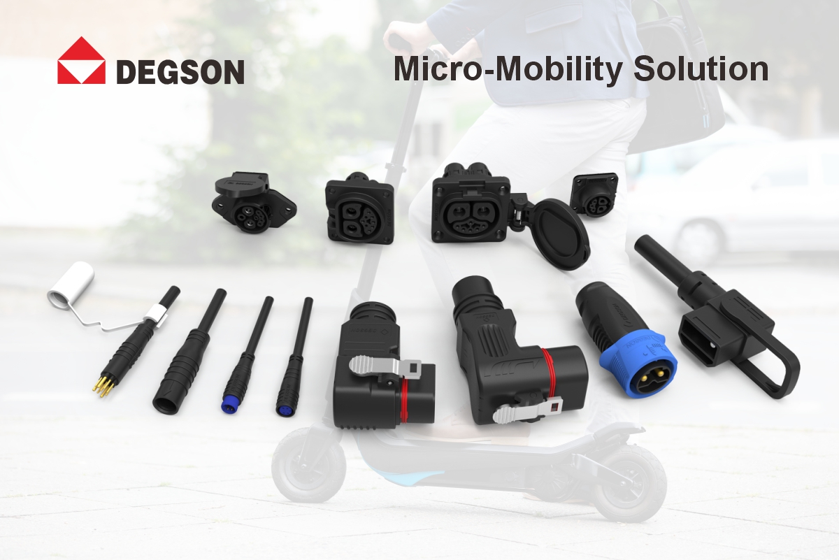
DEGSON Battery Interface Series Overview
The table below summarizes the DEGSON micro-mobility battery interface series referenced in this article. Ratings not listed here (voltage, exact pin count, dimensions) must be confirmed in the product datasheet — this table orients series selection, it does not replace the datasheet.
| Series | Interface role | Current class | Signal channel | Mounting | Typical application |
|---|---|---|---|---|---|
| EBBH 80A | Battery discharge + signal integrated | 80A power | 2A signal | Panel / cable | Battery discharge with BMS signal |
| EBBH 120A | High-power battery discharge | 120A power | Per model | Panel / cable | High-power e-motorcycle |
| EBBL / EBBM / EBBR | Battery interface | Varies by model | Varies by model | Panel / cable | Different battery pack layouts and current classes |
| EBC | Charging inlet (flap cover) | Varies by model | N/A | Panel | Separate charging port on vehicle |
| EBSC | Charging plug / receptacle | Varies by model | N/A | Cable / panel | Charging adapter applications |
| EBI | Signal integration | Signal only | Multi-pole | Panel mount | Panel-mounted signal consolidation |
Why Battery Compartments Are Shrinking While Connector Requirements Grow
The trend:
Electric two-wheeler design is moving toward lighter, more compact vehicles. Battery packs are being designed with higher energy density cells, allowing the same range in a smaller volume. The battery compartment — the space allocated for the battery and its connector — is shrinking accordingly. At the same time, the battery interface must handle more functions: the main discharge current (which is increasing as motor power grows), charging current, BMS communication (CAN or UART), temperature sensor signals, and sometimes identification or authentication pins.
The conflict:
Using separate connectors for power and signal means two connector housings, two sets of mounting hardware, and twice the space on the battery pack and vehicle body. This approach does not scale as battery compartments shrink. A separate signal connector also means more wire harness complexity, more potential failure points, and a higher risk of mis-plugging during assembly or after-sales repair.
How DEGSON addresses it:
The DEGSON EBBH 80A battery connector integrates an 80A power channel and a 2A signal channel in a single connector — eliminating the need for a separate signal connector. The DEGSON EBBL, EBBM and EBBR series cover different battery interface layouts and current classes for electric two-wheelers; for each series, specify the rated current, pin count, mounting style, and whether the connector is intended for discharge, charging, or mixed power-signal use so engineers can match the connector to the battery pack architecture. All series use UL94-V0 flame retardant housing materials where confirmed in the datasheet.
Power-Signal Integration: Combining High-Current Power and Low-Voltage Signal in One Connector
The design challenge:
Integrating high-current power pins and low-voltage signal pins in the same connector is not trivial. The power pins generate heat during high-current discharge, and this heat can affect the signal pins if they are placed too close. The power pins also generate electromagnetic interference that can corrupt low-voltage BMS communication signals. The connector must be designed with adequate spacing between power and signal pins, proper grounding, and thermal management that prevents heat buildup from affecting signal integrity.
Pin assignment principles:
When assigning pins in an integrated power-signal connector: place power pins on opposite sides or at the ends of the connector to maximize spacing from signal pins; place ground pins between power and signal pins to provide shielding; ensure that signal pins have adequate creepage and clearance distances from power pins (values depend on the working voltage and pollution degree — confirm the required distances for the specific application); and design the connector so that ground pins mate first and break last during insertion and extraction, providing a safe ground reference before power is applied.
How DEGSON addresses it:
The DEGSON EBBH 80A integrates an 80A power channel and a 2A signal channel in a single compact connector, with pin assignment optimized to separate power and signal. The signal pins are designed for BMS communication and sensor signals. The DEGSON EBBH 120A provides higher current capacity for more powerful e-motorcycle applications. For each model, confirm the exact pin count, rated voltage and pin layout in the datasheet before selection.
Connector Miniaturization and Space Utilization in the Battery Compartment
The space constraint:
The battery compartment is one of the most space-constrained areas on an electric two-wheeler. The connector must fit within the available space between the battery pack and the vehicle body, while also allowing for battery insertion and removal clearance. A bulky connector may require a larger battery compartment cutout, which weakens the body structure and reduces available battery volume. A connector that is too large may also interfere with the battery locking mechanism or the battery removal path.
Design strategies:
To minimize connector space: use integrated power-signal connectors instead of separate connectors; choose a connector with a high space utilization ratio (contact area relative to housing size); consider right-angle or panel-mounted configurations that route wires along the battery pack surface rather than perpendicular to it; and design the battery compartment cutout to match the connector footprint exactly, minimizing wasted space. The actual dimensions (length, width, height) and mounting layout must be taken from the datasheet drawing of the selected model.
How DEGSON addresses it:
The DEGSON EBBL, EBBM and EBBR battery connector series are designed with compact form factors optimized for battery compartment space utilization; confirm the exact dimensions and mounting style per model from the datasheet drawing. The DEGSON EBBH series, with integrated power and signal channels, eliminates the space needed for a separate signal connector. The DEGSON EBI integrated panel connector can also be used at the battery interface to consolidate multiple signal circuits into a single panel-mounted interface, further reducing the total connector footprint in the battery compartment.
Battery Interface Layout: Discharge, Charge and Signal in One Interface
The layout question:
A battery pack typically needs three types of connections: discharge (power from battery to motor/controller), charge (power from charger to battery), and signal (BMS communication, temperature sensing). The question is whether to combine these into one interface or keep them separate. Combining discharge and charge in one connector reduces the number of connectors but means the connector must handle both charge and discharge currents, and the pin assignment must prevent the charger from being connected to the discharge circuit. Keeping them separate adds a second connector but provides electrical isolation between charge and discharge paths.
Design considerations:
For removable batteries that use a separate charging port, DEGSON positions the EBBH series for the discharge interface with integrated signal contacts, while the EBC or EBSC series can be used as dedicated charging inlets. For fixed-battery systems, define whether charge and discharge share one interface or remain separate, then match the connector series to that architecture. Always evaluate the charge and discharge current requirements — if they differ significantly, separate connectors may be more efficient — and ensure that pin assignment and keying prevent cross-connection between charge and discharge circuits.
How DEGSON addresses it:
The DEGSON EBBH series battery connectors are intended for battery discharge interfaces with integrated signal channels, suitable for removable-battery architectures with a separate charging port. The DEGSON EBC (charging inlet with flap cover) and EBSC (charging plug and receptacle) series provide dedicated charging inlet solutions for vehicles that charge through a separate charging port. The DEGSON EBBL, EBBM and EBBR series offer a range of battery interface options for different current and configuration requirements. DEGSON can support custom pin assignment and keying schemes based on the specific battery interface layout requirements.
Multi-Pole Connector Design and Pin Assignment for Battery Packs
The complexity:
As battery packs add more functions — smart BMS, Bluetooth connectivity, GPS tracking, anti-theft systems — the number of signal pins at the battery interface increases. A multi-pole connector with 4, 6, 8 or more pins requires careful design to ensure that each pin is properly assigned, that power and signal pins are adequately separated, and that the connector can be mated and unmated reliably without bending pins or causing intermittent contacts.
Best practices:
For multi-pole battery connectors: use a polarized housing that prevents reverse insertion; assign ground pins to mate first and break last; group signal pins together and separate them from power pins with ground pins; use different pin sizes for power and signal to prevent cross-connection; and ensure that the connector has adequate guidance features (lead-in chamfers or guide posts) to prevent pin bending during blind mating in the battery compartment. Blind-mating reliability depends on the guide geometry and float compensation of the specific model — verify in the datasheet or by sample testing.
How DEGSON addresses it:
The DEGSON EBBH 80A integrates 80A power and 2A signal channels with optimized pin assignment and polarization. The DEGSON EBBL, EBBM and EBBR series provide multi-pole battery connector options with various pin configurations. The DEGSON EBBF swapping connector supports positive/negative insertion with guide post alignment and float compensation — an example of DEGSON multi-pole connector design for battery interfaces where blind mating is required. All DEGSON battery connectors feature guidance features intended for reliable mating in the confined space of the battery compartment; verify the specific model guidance and float performance by datasheet review or sample testing.
Three Checks When Designing a Battery Compartment Connector
1. Evaluate power-signal integration: can high-current power and low-voltage signal be combined in one connector to save space? Verify pin separation, rated voltage and thermal management in the datasheet.
2. Check space utilization: confirm the connector dimensions and mounting style from the datasheet drawing, and verify clearance for battery insertion, removal and locking.
3. Plan the interface layout: will discharge, charge and signal share one connector or be separate? Map each interface role to the connector series (EBBH for discharge+signal, EBC/EBSC for separate charging) and ensure pin assignment and keying prevent cross-connection.
Five Recurring Battery Compartment Connector Mistakes
-
Using separate power and signal connectors — wastes space and increases wire harness complexity.
-
Placing signal pins too close to power pins — heat and EMI corrupt BMS communication.
-
Ignoring battery insertion/removal clearance — connector interferes with the battery path.
-
No polarization or keying on multi-pole connectors — reverse insertion damages pins.
-
Combining charge and discharge without proper pin assignment — charger cross-connection risk.
FAQ
Q1: Can power and signal be integrated in a single battery connector?
A: Yes. The DEGSON EBBH 80A battery connector integrates an 80A power channel and a 2A signal channel in a single compact connector, eliminating the need for a separate signal connector. The pin assignment is optimized to separate power and signal pins, and the signal channel is designed for BMS communication and sensor signals. Integrating power and signal saves battery compartment space, reduces wire harness complexity, and eliminates the risk of mis-plugging a separate signal connector. Confirm the exact pin count, rated voltage and pin layout of the target model in its datasheet before selection.
Q2: What is the difference between the DEGSON EBBL, EBBM, EBBR and EBBH battery connectors?
A: The DEGSON EBBL, EBBM and EBBR series are battery interface connectors covering different battery interface layouts and current classes for electric two-wheelers; for each series, specify the rated current, pin count, mounting style, and whether the connector is intended for discharge, charging, or mixed power-signal use. The DEGSON EBBH series is a higher-current battery connector with integrated power and signal channels — the EBBH 80A combines 80A power with 2A signal, and the EBBH 120A provides higher current capacity for more powerful e-motorcycles. All series use UL94-V0 flame retardant housing materials where confirmed in the datasheet. The choice depends on the battery current requirement, signal pin count, and available space.
Q3: How should pins be assigned in an integrated power-signal battery connector?
A: Place power pins on opposite sides or at the ends to maximize spacing from signal pins; place ground pins between power and signal pins for shielding; ensure adequate creepage and clearance distances (values depend on the working voltage and pollution degree of the application); and design ground pins to mate first and break last. The DEGSON EBBH 80A follows these principles with pin assignment that separates the 80A power channel from the 2A signal channel. For multi-pole connectors, use polarization to prevent reverse insertion and different pin sizes for power and signal to prevent cross-connection.
Q4: Should discharge and charge share the same battery connector or be separate?
A: It depends on the vehicle architecture. For removable batteries that charge off-board through a separate charging port, discharge and charge are typically separate — the DEGSON EBBH series handles discharge while the DEGSON EBC or EBSC series can be used as dedicated charging inlets. For fixed-battery systems, a combined connector may be more space-efficient, but the pin assignment must prevent charger cross-connection. Always evaluate the charge and discharge current requirements and ensure keying prevents incorrect connection. Map each interface role to the connector series before final selection.
Q5: How does a multi-pole battery connector prevent pin bending during blind mating?
A: Through guidance features and polarized housing design. The connector should have lead-in chamfers on the housing and pins, guide posts for alignment, and a polarized shape that prevents reverse insertion. The DEGSON EBBF swapping connector demonstrates this with guide post alignment and float compensation for blind mating in swapping cabinets. The DEGSON EBBH and EBBL/EBBM/EBBR series feature guidance features intended for reliable mating in the confined space of the battery compartment — verify the specific model guidance and float performance by datasheet review or sample testing, because battery insertion is often a blind operation.
References
References used in this article are grouped by type to avoid confusion between company-level management systems, material standards, product safety standards and product datasheets:
-
Product safety standard: UL 4128 — applies only where a connector safety standard is explicitly claimed for a specific DEGSON series or model in its datasheet.
-
Material standard: UL 94 — flammability rating applies only where the specific connector housing material is confirmed as UL 94 V-0 in the datasheet.
-
Company-level quality system: IATF 16949 — a company management system reference; unless explicitly stated in a product datasheet, it should not be interpreted as a product certification for a specific connector series or model.
-
Product data: DEGSON micro-mobility connector product datasheets and drawings — the authoritative source for rated current, rated voltage, pin count, dimensions, mounting layout, mating cycle ratings and extraction force.
Next Step
Visit the DEGSON product pages or datasheets for EBBH, EBBL, EBBM, EBBR, EBC, and EBSC to verify rated current, pin count, interface role, and mounting layout before final connector selection. Contact the DEGSON engineering team if the battery pack requires a custom pin assignment or keying scheme. Visit www.degson.com for the micro-mobility connector catalog, or contact the DEGSON engineering team for battery interface design review.


