Why Do E-Motorcycle Connector Terminals Lose Contact Over Time? Deconstructing Terminal Design, Plating, Contact Resistance and Crimping Process
A connector is only as good as its terminals. The housing, the lock, the seal — all of these are important, but the actual electrical connection happens at the tiny contact point between the male and female terminals. Over time, this contact point degrades: oxidation increases resistance, vibration causes micro-movement that wears the contact surface, and poor crimping at the wire end creates a separate failure point.
DEGSON identifies three primary causes of long-term terminal contact loss in e-motorcycle connectors: degradation at the contact interface (plating wear, unstable normal force, rising contact resistance), environmental stress (temperature cycling, vibration, humidity), and wire termination defects (out-of-spec crimping or soldering). A well-designed terminal with proper plating and adequate normal force will maintain low contact resistance for thousands of mating cycles and years of service, even under vibration. A poorly designed or poorly crimped terminal will fail within months.
This guide covers connector terminals used on electric bicycles, e-motorcycles and electric three-wheelers — including power terminals, signal terminals, crimping process and terminal maintenance. For every DEGSON series mentioned, verify the exact terminal specification in the corresponding datasheet — contact resistance, plating material and thickness, rated current, wire size range, and mating cycle rating — before using this article for selection decisions.
DEGSON Series Overview for Terminal Applications
The table below summarizes the DEGSON micro-mobility series referenced in this article. Numerical values not listed here must be confirmed in the product datasheet — this table is a selection orientation, not a substitute for the datasheet.
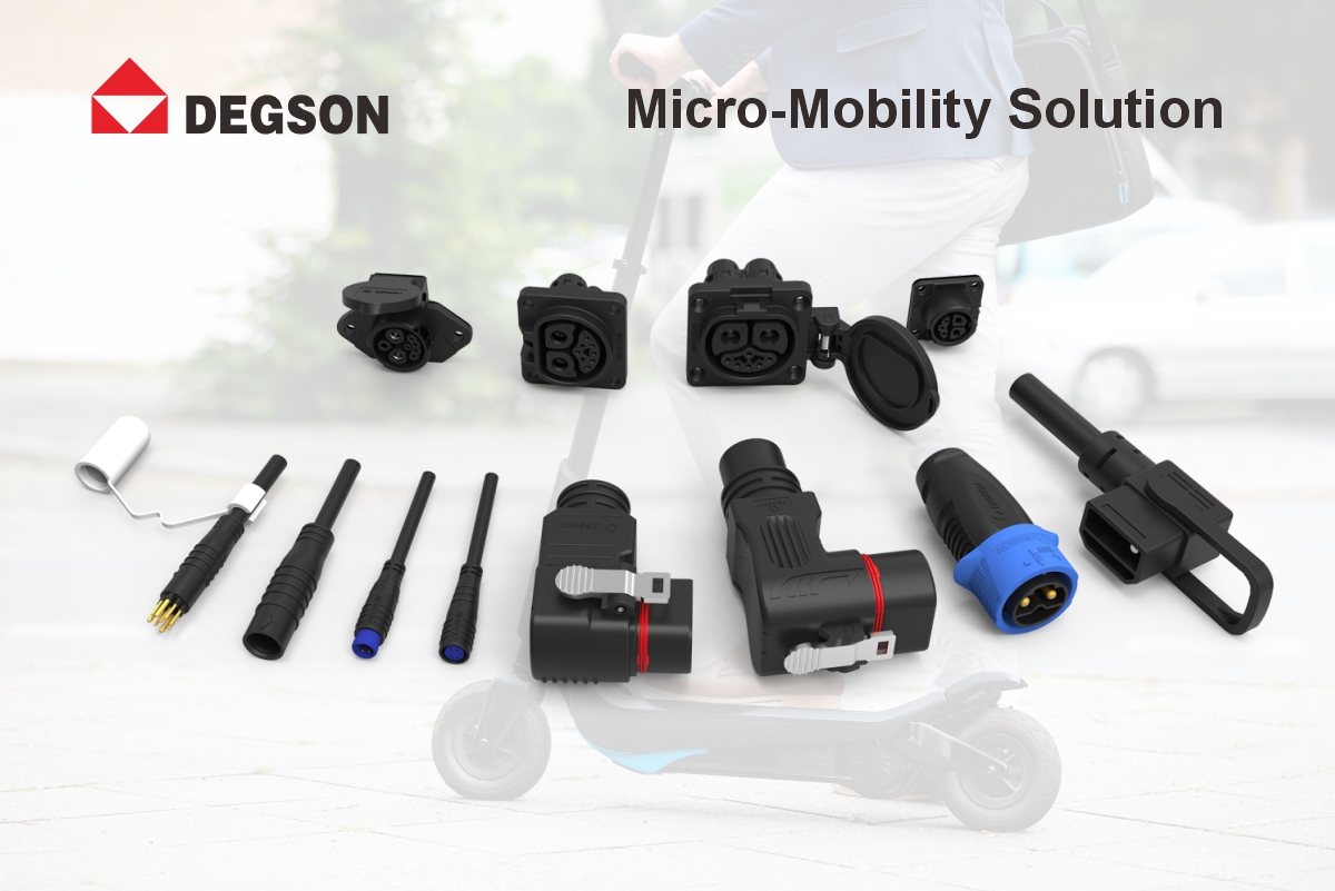
| Series | Application | Termination | Contact resistance | Plating | Locking |
|---|---|---|---|---|---|
| EBBH (80A/120A) | High-current battery discharge, power + signal integrated | Crimp | Per datasheet (sub-mOhm target for power) | Tin (power); gold option for signal | Positive lock |
| EBM | Motor interface, compact | Solder | Per datasheet | Tin | Straight push-pull + protective cover |
| EBS (2-6 core) | Body signal circuits | Crimp | Per datasheet (mOhm range) | Tin standard; gold option | Keyed / polarized housing |
| EBI | Signal wire harness / integrated panel | Pre-crimped harness | Per datasheet | Per application | Panel mount |
Why Terminal Contact Degrades Over Time: Contact Resistance, Oxidation and Fretting
The mechanism:
When two metal surfaces come into contact, the actual contact area is much smaller than it appears — only the highest peaks on the surface touch. Current flows through these tiny contact points, and the resistance at these points (called contact resistance) generates heat. Over time, several things happen: oxidation forms on the contact surfaces, increasing resistance; temperature cycling causes the metals to expand and contract, changing the contact pressure; and vibration causes micro-movement between the surfaces, wearing away the plating and exposing the base metal to oxidation.
What to monitor:
Contact resistance should be measured in milliohms (mOhm) for signal terminals and sub-milliohms for high-current power terminals. A significant increase in contact resistance over time — especially under load — is the earliest warning sign of terminal degradation. For high-current connectors, even a few milliohms of additional resistance can generate significant heat (P = I-squared x R), accelerating further degradation in a vicious cycle. Contact resistance values quoted for any DEGSON terminal must be read against the measurement conditions (test current, open-circuit voltage, temperature) stated in the datasheet.
How DEGSON addresses it:
For each DEGSON series mentioned in this article, verify the exact terminal specification in the corresponding datasheet, including contact resistance, plating material and thickness, rated current, wire size range, and mating cycle rating. Example series covered here include DEGSON EBBH power connectors, EBS signal connectors, and EBM motor connectors. The datasheet specifies the test conditions under which contact resistance is measured.
Terminal Plating: Tin vs. Gold, Thickness and Durability
The options:
Connector terminals are typically plated with either tin (Sn) or gold (Au), sometimes with a nickel (Ni) underlayer. Tin plating is the most common — it is inexpensive, provides good conductivity, and forms a protective oxide layer that is easily broken through during mating. Gold plating is more expensive but provides superior corrosion resistance, lower and more stable contact resistance, and better performance in low-voltage signal circuits where the contact force may not be sufficient to break through tin oxide.
Selection criteria:
For high-current power terminals (battery, motor, charging), tin plating is generally sufficient and cost-effective — the high current and contact force help break through any oxide layer. For low-voltage signal terminals (BMS communication, sensors, switches), especially in humid or corrosive environments, gold plating may be preferred for its stable low contact resistance. Plating thickness matters: too thin and it wears through quickly; too thick and it adds cost without benefit. Plating material and thickness must be confirmed per series and model from the datasheet — DEGSON specifies plating based on application requirements.
How DEGSON addresses it:
DEGSON specifies terminal plating based on application requirements — power terminals (EBBH, EBM) use appropriate tin plating for high-current performance, while signal terminals (EBS, EBI) can be specified with gold plating for critical low-voltage circuits. Confirm the exact plating material and thickness for the specific model in its datasheet before release.
Normal Force and Contact Spring Design
Why it matters:
Normal force — the force with which the male and female terminals press against each other — is the single most important parameter for contact reliability. Too little normal force and the contact resistance is high and unstable, vibration causes micro-movement, and the terminal is susceptible to fretting corrosion. Too much normal force and the mating force is excessive, making assembly difficult and accelerating wear during mating cycles. The ideal normal force balances low contact resistance with reasonable mating force and long mechanical life.
Design principles:
Contact springs are typically designed as cantilever beams, torsion springs or multi-finger contacts. The spring material (usually copper alloy such as beryllium copper or phosphor bronze) must maintain its spring force over the operating temperature range and after thousands of mating cycles. The contact geometry — the shape and size of the contact point — determines the actual contact area and the current density. For high-current terminals, a larger contact area and multiple contact points help distribute current and reduce heating.
How DEGSON addresses it:
DEGSON connector terminals use optimized contact spring designs with appropriate normal force for each application. Mechanical life (mating cycles) and normal-force-related specifications are listed per model in the datasheet — for example, the DEGSON EBBH series battery connector specifies a mating cycle rating of no less than 3000 cycles with an extraction force greater than 50N (confirm the exact value for the target model). Verify the mechanical life and contact resistance retention data in the datasheet before selection.
Fretting Corrosion Under Vibration: The Hidden Terminal Killer
The mechanism:
Fretting corrosion is a specific type of contact degradation that occurs when two metal surfaces in contact experience small amplitude oscillations (micro-movement) under load. On an electric two-wheeler, vibration from the motor, road surface and wind can cause micro-movement at the terminal contact interface. This micro-movement wears away the plating, exposing the base metal (usually copper or copper alloy), which then oxidizes. The oxide particles are abrasive, causing more wear, which causes more oxidation — a self-accelerating cycle. The result is a rapid increase in contact resistance, often appearing as an intermittent fault that is difficult to diagnose.
Prevention strategies:
Fretting corrosion is prevented by: adequate normal force to prevent micro-movement, gold plating (which does not form abrasive oxide), contact lubricants that reduce friction and wear, and connector locking mechanisms that prevent relative movement between the mating halves. For high-vibration locations (motor, wheel hub, frame), verify that the connector has positive locking and that the terminal normal force is sufficient to resist vibration-induced micro-movement.
How DEGSON addresses it:
DEGSON connectors are designed with positive locking mechanisms and adequate terminal normal force to prevent vibration-induced micro-movement — for example, the DEGSON EBM motor connector, intended for the high-vibration motor environment, uses straight push-pull mating with secure retention, and the DEGSON EBBH series specifies an extraction force above 50N to resist loosening under vehicle vibration (confirm the exact value per model in the datasheet).
Crimping Process: Crimp Height, Pull-Out Force and Quality Control
The failure point:
The crimp — the mechanical and electrical connection between the terminal and the wire — is often the weakest link in the connector system. A poorly crimped terminal has high resistance at the wire-terminal interface, generates heat under load, and may eventually fail from fatigue or corrosion. Common crimping defects include: incorrect crimp height (too loose = high resistance, too tight = damaged wire strands), incomplete wire insertion (strands not fully inside the crimp barrel), damaged insulation, and inconsistent crimping from worn or uncalibrated tooling.
Quality control:
Crimping quality should be controlled through: crimp height measurement (the primary quality metric — each terminal and wire gauge has a specified crimp height range), pull-out force testing (the terminal must withstand a specified pull force without separating from the wire), visual inspection of crimp form (no damaged strands, proper insulation grip), and regular calibration of crimping tools. For high-volume production, use crimping machines with crimp force monitoring that automatically rejects out-of-spec crimps. Always follow the terminal manufacturer crimping specifications — do not guess the crimp height.
How DEGSON addresses it:
For any DEGSON crimp terminal used in e-motorcycle applications, use the series-specific datasheet or application note to confirm the approved wire size range, target crimp height range, minimum pull-out force requirement, and recommended tooling before production release. For solder-terminated types such as the DEGSON EBM motor connector, the datasheet specifies soldering parameters (temperature below 350C, time under 3 seconds). For customers who prefer ready-to-install harnesses, the DEGSON EBI series offers signal wire harness solutions with pre-terminated connectors.
Three Checks for Terminal and Crimping Reliability
1. Verify terminal specifications in the datasheet: contact resistance (with measurement conditions), plating material and thickness, normal force, rated current, wire size range, and mating cycle rating.
2. Check fretting resistance: for high-vibration locations, verify positive locking (e.g., extraction force specification), adequate normal force, and appropriate plating (gold for critical signal circuits).
3. Control crimping quality: use the manufacturer specified crimp height for the wire gauge, measure pull-out force, calibrate tools regularly, and use crimp force monitoring for high-volume production.
Five Recurring Terminal and Crimping Mistakes
-
Ignoring contact resistance increase — early warning sign of terminal degradation is missed.
-
Using tin plating for low-voltage signals in humid environments — oxide causes intermittent contact.
-
Inadequate normal force under vibration — fretting corrosion causes rapid contact degradation.
-
Incorrect crimp height — too loose causes high resistance, too tight damages wire strands.
-
No crimp quality control — relying on visual inspection instead of crimp height and pull-out force measurement.
FAQ
Q1: What contact resistance should e-motorcycle connector terminals have?
A: Contact resistance depends on the terminal type and current rating. High-current power terminals (battery, motor, charging) should have sub-milliohm to low-milliohm contact resistance, because even a few milliohms generates significant heat at high current (P = I-squared x R). Signal terminals typically have contact resistance in the milliohm range. For any DEGSON terminal (EBBH power, EBS signal, EBM motor), read the contact resistance value together with the measurement conditions (test current, voltage, temperature) stated in the series datasheet, and monitor it over time — a significant increase is the earliest warning of terminal degradation.
Q2: Should connector terminals be tin-plated or gold-plated?
A: For high-current power terminals (battery, motor, charging), tin plating is generally sufficient and cost-effective — the high current and contact force help break through any oxide layer. For low-voltage signal terminals (BMS communication, sensors, switches), especially in humid or corrosive environments, gold plating provides superior corrosion resistance and more stable low contact resistance. DEGSON specifies plating based on application requirements: power terminals (EBBH, EBM) use tin plating; signal terminals (EBS, EBI) can be specified with gold for critical circuits. Confirm the exact plating material and thickness for the target model in its datasheet.
Q3: How does vibration cause terminal contact failure, and how is it prevented?
A: Vibration causes micro-movement at the terminal contact interface, leading to fretting corrosion — the plating wears away, base metal oxidizes, and oxide particles accelerate further wear. This causes a rapid increase in contact resistance, often as an intermittent fault. Prevention: adequate normal force, gold plating for critical signals, contact lubricants, and positive locking to prevent relative movement between mating halves. For example, the DEGSON EBBH series specifies an extraction force above 50N to resist loosening under vehicle vibration, and the DEGSON EBM motor connector is intended for high-vibration motor environments with secure retention — confirm the exact values per model in the datasheet.
Q4: What crimping parameters should be controlled for connector terminals?
A: The primary quality metric is crimp height — each terminal and wire gauge has a specified crimp height range that must be measured with a crimp height micrometer. Additional controls: pull-out force testing (terminal must withstand specified force without separating from wire), visual inspection (no damaged strands, proper insulation grip), and regular tool calibration. For high-volume production, use crimp force monitoring to automatically reject out-of-spec crimps. For any DEGSON crimp terminal, use the series-specific datasheet or application note to confirm the approved wire size range, target crimp height range, minimum pull-out force, and recommended tooling before production release.
Q5: What soldering parameters apply to DEGSON motor connector terminals?
A: The DEGSON EBM motor connector uses soldered terminal wiring. Use a temperature-controlled soldering iron with temperature below 350C and soldering time not exceeding 3 seconds to avoid insulator deformation or motor winding damage. For high-volume production, configure soldering fixtures to ensure consistency. Before production, train workers on terminal alignment and soldering temperature control. DEGSON provides recommended soldering parameters in the EBM product datasheet. For customers who prefer pre-assembled solutions, the DEGSON EBI series offers signal wire harness solutions with pre-terminated connectors.
References
References used in this article are grouped by type to avoid confusion between company-level management systems, material standards, product safety standards and product datasheets:
-
Product safety standard: UL 4128 — applies where a connector safety standard is explicitly claimed for a specific DEGSON series or model in its datasheet.
-
Material standard: UL 94 — flammability rating applies only where the specific connector housing material is confirmed as UL 94 V-0 (e.g., DEGSON micro-mobility housings specified V-0 in datasheets).
-
Company-level quality system: IATF 16949 — a company management system reference; unless explicitly stated in a product datasheet, it should not be interpreted as a product certification for a specific connector or terminal.
-
Product data: DEGSON micro-mobility connector product datasheets and application notes — the authoritative source for contact resistance, plating, current rating, wire size range, crimp height range and mating cycle ratings.
Next Step
Review the DEGSON product page and datasheet for the exact EBBH, EBM, EBS, or EBI model used in your design, then confirm contact resistance, plating specification, locking method, wire termination requirements, and validation test conditions before release. Visit www.degson.com for the micro-mobility connector catalog and terminal application notes, or contact the DEGSON engineering team for terminal specification and crimping process support.


