How to Choose the Right DIN Rail: A Selection Guide for Electrical Cabinet Assembly (2026)
To choose a DIN rail, first decide what the rail must do — mechanical mounting only, or mounting plus protective earthing. Then select the profile and size from IEC 60715 (35 × 7.5 mm top-hat for most components, 35 × 15 mm where load or span is higher), then the material and surface finish, and finally whether cut-to-length, pre-punched or pre-assembled rails save more assembly time than they cost. If the rail is part of an earthing path, check its equivalent copper cross-section and short-time withstand current under IEC 60947-7-2 rather than assuming any metal rail is adequate.
Define the Rail's Function Before Its Size
A DIN rail is a standardized metal mounting rail that holds circuit breakers, relays, PLCs, power supplies and terminal blocks inside a cabinet or distribution box. "DIN" refers to the Deutsches Institut für Normung. The rail dimensions were later carried into European (EN 60715) and international (IEC 60715) standards, which is why a 35 mm rail from one supplier accepts components from another.
The rail's primary job is mechanical support. It is not a busbar and should not be planned as a current-carrying conductor. Because it is metal, however, it is usually bonded to the enclosure and used to earth the components that clip onto it — for example, PE terminal blocks that contact the rail foot directly. That second role changes the material decision, so record it at the start of the design: "mounting only" or "mounting + earthing".
Select the Profile and Size per IEC 60715
Three cross-sections are still in use:
-
Top-hat (TH, also called Ω or TS 35): the dominant form in current cabinets.
-
C-section (C30/C40/C50): symmetric C shape, now uncommon in new designs.
-
G-section (G32): asymmetric, 32 mm wide, mainly on legacy equipment.
For top-hat rails, IEC 60715 defines the 35 mm width with two heights:
| Profile | Typical thickness | Typical use |
|---|---|---|
| 35 × 7.5 mm | 1.0 mm | Default for breakers, terminal blocks, relays, rail power supplies |
| 35 × 15 mm | 1.5 mm or 2.3 mm | Heavier components, longer unsupported spans, stricter deflection limits |
A narrower 15 mm rail (TS 15) suits very small components but is far less interchangeable than TS 35. Before ordering, check three points against each component datasheet: rail width, rail height (some components need the 15 mm depth for clearance or stability) and whether a slotted rail is acceptable for the fixing method.
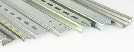
Choose Steel, Aluminum or Copper by Mounting vs Earthing Role
Material follows the function defined in the first step.
Steel (zinc-plated, usually passivated) is the default. It is strong, low-cost and widely stocked, and it covers almost all mounting-only applications. Its conductivity and short-time withstand are the lowest of the three.
Aluminum conducts better than steel and is lighter, but its oxide layer raises contact resistance, so contact surfaces need attention when the rail is in an earthing path.
Copper has the highest conductivity and short-time withstand current. It is used where the rail itself must carry earth-fault current, at a much higher material cost.
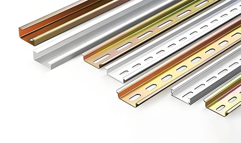
When a rail serves as the conductor for PE terminal blocks, manufacturers rate it by an equivalent copper cross-section and a 1 s short-time withstand current per IEC 60947-7-2 (120 A/mm² × cross-section). Published values:
| Rail | Material | Equivalent Cu cross-section | 1 s short-time withstand |
|---|---|---|---|
| 35 × 7.5 mm | Copper | 50 mm² | 6 kA |
| 35 × 7.5 mm | Aluminum | 35 mm² | 4.2 kA |
| 35 × 7.5 mm | Steel, zinc-plated | 16 mm² | 1.92 kA |
| 35 × 15 mm | Aluminum | 70 mm² | 8.4 kA |
Two rules follow. First, a steel rail can earth PE terminal blocks up to its rated equivalent cross-section, but steel may not be used as a PEN conductor under IEC 60947-7-2. Second, automation vendors' installation guides commonly specify zinc-plated, chromate-passivated steel rail for equipment earthing, because untreated aluminum can oxidize and give unstable earth resistance (see the IEEE PES white paper on DIN rail). Higher conductivity on paper does not guarantee a stable earth contact over years of service.
In procurement, request the electrical data sheet for the exact profile, thickness and material rather than reusing a value from a different rail.
Specify Custom Rails with a Complete Drawing
Standard 1 m or 2 m lengths suit most projects. Customization becomes worthwhile when cabinets are non-standard, layouts are tight or holes must match a fixed pattern. A complete inquiry should define:
-
Profile and cross-section: TH, C or G; width, height and material thickness. 35 × 7.5 × 1 mm is the usual baseline; heavier cabinets may need a taller or thicker section for stiffness.
-
Length and tolerance: cut-to-drawing lengths with a stated tolerance. On high-volume lines, cut consistency and burr-free end faces affect takt time.
-
Slotting or punching: slotted rails allow flexible fixing and cable-tie routing; solid rails give a continuous surface. State hole shape, pitch and edge distance on the drawing.
-
Surface finish: zinc plating for standard steel; stainless steel (304/316L) or a suitable passivation for humid, outdoor or corrosive locations, with corresponding cost and lead-time changes. Record the finish in the part documentation so batches stay consistent — finish variation affects both corrosion and earth contact.
-
Quantity, packaging and labeling.
A supplier that offers controlled drawings, sample approval and repeat-order consistency makes a custom rail easier to manage as a stable part number.
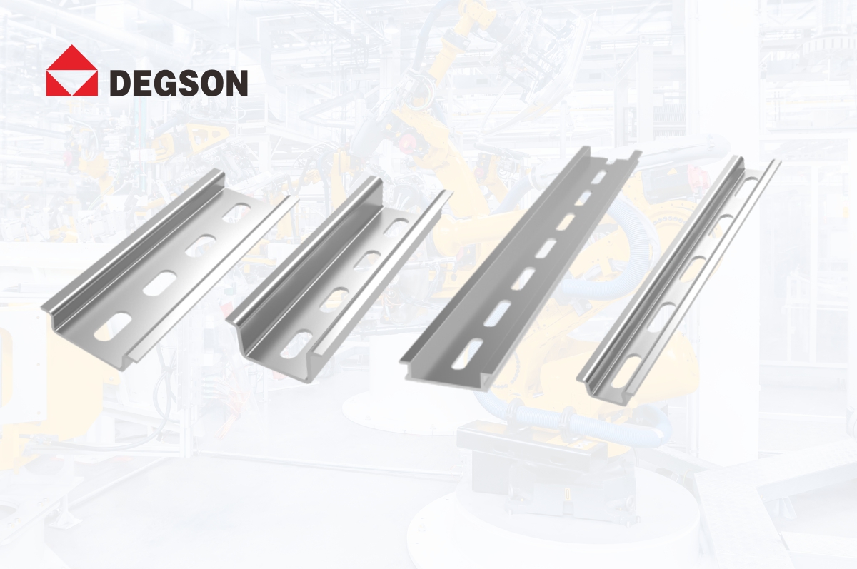
DEGSON lists its NS35 top-hat rails, including the NS35/7.5-1000-00A(H), among the accessories for its DIN rail terminal blocks (product search); DEGSON terminal block datasheets such as DS10 name this rail as the mounting accessory. For the rail's material, thickness, finish and earthing data, or for a custom length or slot pattern, contact DEGSON technical support with your drawing.
Decide When Pre-Assembled DIN Rails Pay Off
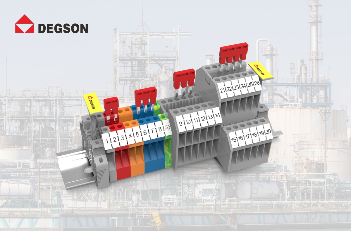
In the conventional workflow, the panel builder buys bare rails, terminal blocks, end plates, partitions, jumpers and markers separately and assembles them in the shop. The hidden costs are incoming inspection of many loose parts, storage, assembly labor, line stops for missing parts and positioning errors.
A pre-assembled rail is delivered with terminals and accessories mounted to the drawing, marked and continuity-checked. Its effects:
-
Purchasing and inventory: dozens of loose part numbers become one finished part number, deliverable in batches against the work-order schedule. Repeat cabinet types get a fixed number, reducing re-checking and mismatch risk.
-
Assembly and quality: the rail is installed as one unit, removing terminal-by-terminal mounting, spacing, end plates and marking inside the cabinet. Less-experienced staff can install rail modules and start wiring. Actual time savings depend on rail complexity and the builder's automation level, so compare quotes against your own measured assembly hours.
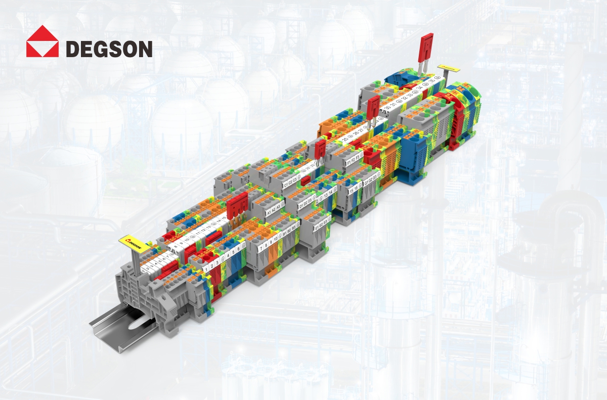
Pre-assembly is not always the better choice. For highly standardized cabinets with strong in-house capacity and favorable loose-part pricing, in-house assembly can remain cheaper. It pays off most for builders trying to shorten lead time, reduce work-in-progress and keep quality stable across many low-volume variants.
DEGSON supplies the terminal blocks that populate these rails — for example the push-in DS2.5 (IEC 800V/24A, UL 600V/20A, 0.14–4 mm²) and the screw-type DC2.5 (IEC 800V/24A, UL 600V/25A), both to IEC 60947-7-1 — and offers pre-assembled rails as a value-added service, quoted against the customer's rail drawing and terminal list.
FAQ
Can a steel DIN rail be used for protective earthing?
Yes, for PE terminal blocks within its rated equivalent cross-section — 16 mm² and 1.92 kA for 1 s for a typical zinc-plated 35 × 7.5 mm steel rail. It may not be used as a PEN conductor.
Should I choose 35 × 7.5 mm or 35 × 15 mm?
Start with 35 × 7.5 mm, which most components are designed for. Move to 35 × 15 mm when components are heavy, spans between fixing points are long, or a component datasheet requires the extra depth.
Next step: search DEGSON NS35 rails and DIN rail terminal blocks at degson.com.cn, 内部工具 datasheets and CAD, or contact DEGSON technical support with your rail drawing and terminal list for rail data, custom rails or pre-assembled rail support.
References
-
IEC 60715: Dimensions of low-voltage switchgear and controlgear — standardized mounting on rails. https://webstore.iec.ch/en/publication/3678
-
IEC 60947-7-2: Protective conductor terminal blocks for copper conductors. https://webstore.iec.ch/en/publication/2862
-
IEEE PES NPEC SC-2, DIN-Rail in the Electrical Control Cabinet and Junction Box. https:SC-2Mgt08-2_Att9-WP_DIN-Rail.pdf


