Energy Storage Connector Selection by System Level: Module, Cluster, PCS and Service Disconnect (2026)
Choose a battery energy storage connector by first fixing where the connection sits (inside a module, between modules in a cluster, between the cabinet and the PCS, or at the service disconnect), then the voltage and continuous current at that point, and finally the safety redundancy it needs: keying against mis-mating, secondary locking, sealing, temperature-rise margin and a defined, de-energized disconnect point. Connectors for battery interconnection are evaluated to UL 4128 and TÜV Rheinland 2PfG 2740 — neither covers breaking current under load.
This guide covers high-voltage, high-current connections in residential, commercial & industrial (C&I) and utility-scale battery storage. It does not cover low-voltage signal harnesses, PV string connectors or systems above 1500V DC.
Map the Five Connection Types in a Storage Cabinet First
From cell to PCS, a typical storage cabinet carries five connection needs at once: single-pole high-current power connections, the manual service disconnect (MSD, or FMSD with fuse), multi-pole communication connectors, RJ45 wall-penetration guards for BMS data, and series/parallel power harnesses. They sit at different levels and fall under different requirements, so listing them before choosing parts prevents the most common error — selecting one "storage connector" and using it everywhere.
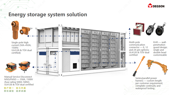
Figure 1: Connection types in a storage cabinet. Single-pole high-current connectors (50–450A, 1500V), MSD (350A, 1500V), fused FMSD, multi-pole communication connectors (8/12/24 pin), RJ45 wall-penetration guard and custom-length series/parallel harness.
The current and voltage at each level depend on cell capacity, cluster configuration and PCS rating, so the ranges below are typical starting points, not limits. Always size from your own single-line diagram.
Intra-Module: Density and Keying Decide the Choice
The module or pack is the smallest serviceable unit and has the most connection points in the least space. Currents here are moderate, so the selection risk is not ampacity but mis-mating: a positive lead plugged into the wrong position can short a cell group or create circulating current between modules. Specify mechanical keying or color coding that makes wrong insertion physically impossible, touch-safe contacts for assembly at partial voltage, and flame-retardant housings (PA66 at UL 94 V-0 is common). Signal and sense connections at this level are typically separate, smaller connectors routed to the BMS.
Battery Cluster: Locking, Sealing and Termination at 1500V
When packs are connected in series into a cluster, voltage climbs to 1000–1500V DC and cluster current to 150–300A. Two failure modes dominate: loosening under transport and operating vibration, and moisture or dust ingress at the mating face. A cluster connector therefore needs a positive primary lock plus a secondary lock, a sealed mating interface, and polarity coding so positive and negative cannot be swapped.
As a verifiable example, DEGSON's ESS-300A-95 socket is rated 1500V / 300A with copper-busbar termination (the mating ESP-300A-95 plug crimps a 95 mm² cable); the product pages list IP67, −40 °C to +125 °C, contact resistance ≤0.5 mΩ, insulation resistance >5000 MΩ and a PA housing rated UL 94 V-0. Those four numbers — voltage, current, cross-section and contact resistance — are the minimum to compare across any vendor's datasheets.
Flexible busbars for very short, very high-current links
As cells move from 280Ah to 314Ah and larger formats, cluster current and cable size grow. At very short distances, thick cable becomes hard to crimp, needs a large bend radius and is difficult to route neatly. A flexible busbar with an insulated, sealed jacket solves that segment. According to DEGSON product literature, its flexible busbar (part number S-ESPP-12-OR-0204-BK-A00A) is rated up to 1500V / 450A and customized to the cabinet layout.
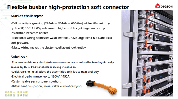
Figure 2: Flexible busbar high-protection soft connector for very short, high-current links.
Cabinet to PCS: Temperature Rise Is the Real Rating
The link between the battery cabinet and the PCS or DC combiner carries the highest current in the system, commonly several hundred amps at 1500V. The practical limit is rarely "can the contact carry it" but "how hot does it get doing so". Every 0.1 mΩ of extra contact resistance at 300A adds 9 W of heat at that joint (P = I²R), and that heat ages insulation and seals over years.
Ask for temperature-rise test data at your actual conductor size and highest ambient temperature, not just the catalogue rating, and keep continuous current comfortably below the rated value. A 20–30% margin is a common engineering practice, not a standard requirement — your own thermal analysis and the system standard govern.
Crimp quality is part of the connector rating
A connector's datasheet values assume a correct termination. A poor crimp raises contact resistance and turns directly into extra temperature rise. The cross-sections below show the difference: NG samples leave gaps between strands and barrel with offset crimp marks; OK samples show a tightly compacted conductor and even crimp.
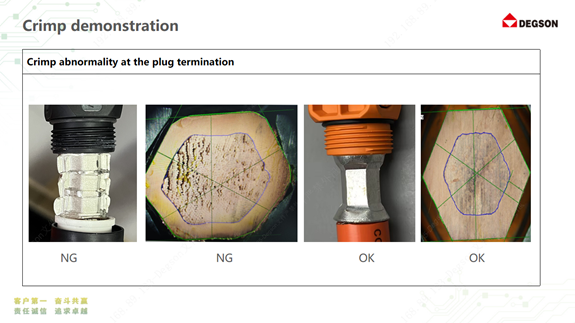
Figure 3: Crimp cross-section comparison — NG (voids, insufficient contact area) vs OK (tight, even compaction).
When approving a connector, approve the crimp tool, die set and cross-section inspection criteria with it. DEGSON provides crimp specifications and cross-section verification support for its storage connectors.
Service and Safety: MSD and HVIL Do Not Break Load Current
Stored energy cannot be switched off at the cells, so servicing needs a defined isolation point. An MSD (manual service disconnect) lets a technician physically open the high-voltage string; an FMSD adds a fuse in that path. HVIL (high-voltage interlock) is a low-voltage pilot loop routed through the connector: when the connector starts to separate, the pilot opens first and signals the BMS to open its contactors before the power contacts part.
This sequence matters because UL 4128 covers intercell and intertier connectors that are not intended for connection or disconnection under load. The MSD and the power connectors are isolation devices, not switches — the procedure must be: stop the PCS, open contactors via the BMS, then pull the MSD.
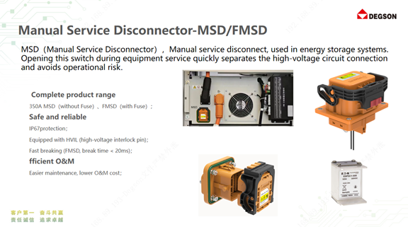
Figure 4: MSD (without fuse, IP68, with HVIL pins) and FMSD (with fuse, IP67).
DEGSON's MSD-350A is rated 1500V / 350A, IP68, −40 °C to +125 °C (with derating), UL 94 V-0, with HVIL pins and a secondary lock; UL and TÜV certification is listed on the product page. The fused FMSD is a separate, lower-voltage part rated 500V DC / 200A, IP67, −40 °C to +125 °C, with fuse ratings and brands selectable; according to DEGSON product literature, its break time is under 20 ms. Note the voltage difference: an FMSD rated 500V DC suits pack-level isolation, not a 1500V cluster string — check the rated voltage of any service disconnect against the point where it is installed.
Checklist: Matching Connector to Level
- Intra-module (≤150A, tight space): keyed, touch-safe connector, UL 94 V-0 housing.
- Battery cluster (1500V, 150–300A): single-pole connector with secondary lock, IP67, polarity coding, datasheet contact resistance.
- Cabinet to PCS (300A and above): temperature-rise report at your conductor size and ambient, current margin, approved crimp process.
- Every live string: MSD or FMSD with HVIL, operated only after the BMS has opened the contactors.
- Certification: connector evaluated to UL 4128 and/or TÜV Rheinland 2PfG 2740; system evaluated to IEC 62619 and UL 1973 (and UL 9540 at system level for North America). Request certificate numbers and check them in the issuer's database.
FAQ
Can PV MC4-type connectors be used between battery packs?
No. PV connectors are evaluated to IEC 62852 for photovoltaic DC circuits, typically for string currents in the tens of amps, and cannot be cross-mated across brands. Battery interconnection uses connectors evaluated to UL 4128 or 2PfG 2740 at the cluster's current.
Which certificates should a 1500V storage connector carry?
At connector level, UL 4128 for North America and TÜV 2PfG 2740 is widely requested elsewhere; at system level, IEC 62619 and UL 1973 / UL 9540. Confirm against the target market's requirements and verify certificate numbers with the issuer.
References
- UL Standards & Engagement — UL 4128, Intercell and Intertier Connectors for Use in Electrochemical Battery System Applications
- IEC — IEC 62619, Safety requirements for secondary lithium cells and batteries for industrial applications
- UL Standards & Engagement — UL 1973, Batteries for Use in Stationary and Motive Auxiliary Power Applications
- TÜV Rheinland — 2PfG 2740, Connectors for lithium battery energy storage systems — safety requirements and tests
- DEGSON — 250A–300A energy storage connector series
Take the Next Step
Once you have fixed the level, voltage and continuous current for each connection, browse the DEGSON energy storage connector series to datasheets and CAD for the matching rating, and contact the DEGSON application engineering team for temperature-rise reports, crimp specifications and certificate copies for the exact configuration you plan to use.


