How Do Mid-Drive and Hub Motors Differ in Their Connector Requirements? Deconstructing Vibration, Temperature and Wiring Layout Across Two Motor Architectures
DEGSON recommends different connector priorities for the two motor architectures: hub motors need compact, positive-lock connectors for sealed, high-vibration wheel cavities, while mid-drive motors need thermally derated connectors with protected routing away from the chain line. The two architectures dominate electric two-wheelers, and they stress the motor connector very differently: a hub motor mounts the motor inside the rear wheel — the connector lives in a sealed, heat-retaining cavity and is bolted to the vibration source itself; a mid-drive motor sits at the frame center near the bottom bracket — the connector is more exposed to airflow and road spray, and it receives vibration transmitted through the frame and drivetrain rather than directly from the motor casing. Connector failures that appear identical in the service bay — intermittent power, melted terminals, cracked housings — often have different root causes depending on which architecture they came from.
For hub-motor installations, prioritize vibration retention (positive locking), compact size for the sealed wheel cavity, and a protective cover for the exposed male terminals. For mid-drive installations, prioritize thermal derating for sustained load, protection against road spray exposure, and a wiring path that avoids the chain line and moving drivetrain parts. In the DEGSON range, the EBM e-motor connector (compact, straight push-pull, protective cover, operating temperature -25C to +80C) and the EBIC motor power connector (press-locking, power and signal) cover both architecture requirements; confirm the exact temperature range, current rating, IP rating and locking specification for the target part number in its datasheet.
This guide covers motor connectors on mid-drive and hub-motor electric bicycles, e-motorcycles and electric three-wheelers — including motor-to-controller power and signal connections. Model-level parameters quoted in this article are taken from the DEGSON product datasheet; values not listed here must be confirmed in the datasheet.
DEGSON Motor Connector Comparison: EBM vs. EBIC
The table below compares the two DEGSON motor connector series across the parameters engineers extract first. Values marked 'datasheet' must be confirmed per part number.
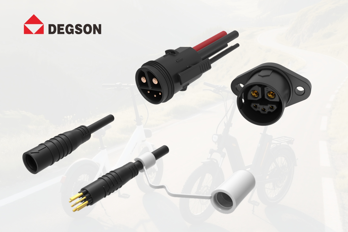
| Parameter | DEGSON EBM e-motor connector | DEGSON EBIC motor power plug and socket |
|---|---|---|
| Recommended architecture | Hub motor (e-bike, light e-motorcycle), compact motor compartments | Higher-power motor applications, motor-to-controller power and signal |
| Rated current (A) | Confirm per part number (datasheet) | Confirm per part number (datasheet) |
| Rated voltage (V) | Confirm per part number (datasheet) | Confirm per part number (datasheet) |
| IP rating | Confirm per part number (datasheet) | Confirm per part number (datasheet) |
| Operating temperature | -25C to +80C (per datasheet) | Confirm per part number (datasheet) |
| Locking type | Straight push-pull, secure retention, protective cover on male side | Press-locking structure |
| Mating cycles | Confirm per part number (datasheet) | Confirm per part number (datasheet) |
| Wire size / pin count | Confirm per part number (datasheet) | Confirm per part number (datasheet) |
| Service access | Tool-free unmate, cover protects terminals during assembly | Release by deliberate press |
Mid-Drive vs. Hub Motor: What Changes at the Connector
The two architectures:
A hub motor integrates the motor into the rear (or front) wheel hub, driving the wheel directly. The motor connector is mounted on or near the motor casing inside the wheel cavity, and the wiring runs along the rear swing arm. A mid-drive motor mounts at the frame center, typically at the bottom bracket, driving the crankshaft or a transmission; the connector sits near the frame center and the wiring runs along the down tube or seat tube toward the controller.
Why it matters:
Because the mounting location and the vibration path differ, the connector requirements differ. Hub-motor connectors need to survive vibration from the wheel itself, sealed-cavity heat, and blind installation in a confined cavity. Mid-drive connectors need to survive frame-transmitted vibration, road spray from the front wheel, and proximity to the chain line and drivetrain. Using a connector designed for one architecture in the other often produces field failures that are misdiagnosed as generic connector problems.
How DEGSON addresses it:
The DEGSON EBM e-motor connector is designed for the motor interface environment: it operates over a temperature range of -25C to +80C with UL94-V0 flame retardancy (confirm per part number), uses straight push-pull mating with secure retention suitable for motor-end vibration, includes a protective cover on the male connector, and has a compact structure with high space utilization. The DEGSON EBIC motor power plug and socket uses a press-locking structure, compact and convenient, suitable for motor-to-controller power and signal transmission. Choose the series and part number based on the target architecture and confirm all ratings in the datasheet.
Vibration: Hub Motor Mounts on the Source, Mid-Drive Transmits Through the Drivetrain
Hub motor vibration:
The hub motor is mounted on the wheel, which is the vibration source on rough roads. The connector is bolted directly to the motor casing or the swing arm near the wheel, so it receives the highest amplitude and highest frequency vibration on the vehicle. Over time, this vibration can work a friction-fit connector loose, and the repeated micro-movement can drive fretting corrosion at the terminal interface. Positive locking that engages automatically is therefore a first-order requirement for hub-motor connectors.
Mid-drive vibration:
The mid-drive motor is mounted at the frame center. It still experiences road vibration, but the vibration is transmitted through the frame structure and filtered by the drivetrain — the amplitude at the connector is generally lower than at the wheel. However, the mid-drive location adds two specific stresses: the drivetrain itself generates high-frequency vibration during acceleration and climbing, and the connector sits close to moving drivetrain parts, so a loose connector or a poorly routed wire can be damaged mechanically.
How DEGSON addresses it:
Both DEGSON motor connector series use positive retention rather than friction alone. The DEGSON EBM uses straight push-pull mating with secure retention suitable for motor-end vibration; the DEGSON EBIC uses a press-locking structure that provides positive retention under vibration while remaining compact. Confirm the extraction force and locking behavior of the target part number in the datasheet, and for hub-motor installations verify that the lock engages automatically, because the cavity is often installed blind.
Thermal Environment: Sealed Hub Cavity vs. Frame-Mounted Mid-Drive
Hub motor heat:
The hub motor is enclosed in the wheel, a largely sealed cavity with limited airflow. During prolonged climbing or heavy-load operation, heat accumulates in the cavity, and the connector mounted inside experiences a high ambient temperature. Thermal derating is essential: a connector rated at a given current at 25C may need significant derating at the actual cavity temperature. Heat soak also affects terminal contact resistance over time.
Mid-drive heat:
The mid-drive motor is mounted in the open frame area, exposed to airflow while riding, so its ambient temperature tends to be lower than the sealed hub cavity under the same load. However, mid-drive motors often run at higher sustained power for the same vehicle class (using gear reduction), so the connector must still be checked for thermal derating at the actual operating temperature and sustained duty cycle.
How DEGSON addresses it:
The DEGSON EBM e-motor connector specifies an operating temperature range of -25C to +80C with UL94-V0 flame retardancy (confirm per part number in the datasheet). DEGSON can provide derating guidance based on the actual motor ambient temperature and wire gauge. For higher-power motor applications, the DEGSON EBIC motor power plug and socket provides power and signal transmission with press-locking retention — state the exact current rating and wire size of the selected EBIC part number, and note any thermal derating conditions from the datasheet. Always calculate the derated current at the actual operating temperature of the target architecture, not the room-temperature rating.
Space and Wiring Layout: Rear Swing Arm vs. Frame Center
Hub-motor routing:
On a hub-motor vehicle, the motor connector is inside the wheel cavity, and the wiring runs along the rear swing arm to the controller. The swing arm is a moving component (suspension travel), so the wiring must have enough slack to follow the suspension movement without tension, and the connector must fit the confined cavity with clearance for wheel assembly and disassembly. A bulky connector can interfere with the wheel removal path or the brake assembly.
Mid-drive routing:
On a mid-drive vehicle, the motor connector sits near the frame center, and the wiring runs along the down tube or seat tube to the controller. The main hazards are proximity to the chain line, the crankset and the drivetrain — a wire that sags into the chain can be cut — and exposure to road spray from the front wheel. The routing should keep the connector and wires clear of the chain line and secure them to the frame with clips or grommets.
How DEGSON addresses it:
The DEGSON EBM compact structure with high space utilization fits tight motor compartments, and its straight push-pull operation allows quick connection during assembly. The DEGSON EBIC is compact with a press-locking structure, suitable for motor-end installation where space is constrained. For wiring layout, follow the architecture-specific routing rules above and secure the harness to the frame; DEGSON technical support can review the motor interface layout and wire routing for the target vehicle.
Maintenance and Service Access
Hub-motor service:
Hub-motor connectors are the hardest to reach in service. Servicing the connector means removing the wheel or opening the wheel cavity. This makes reliability and ease of access critical: a connector that fails intermittently inside the hub is expensive to diagnose and repair, and a connector that is difficult to unmate can turn a routine repair into a wheel-off job. The connector should unmate cleanly with the lock released, without tools, and the terminals should survive repeated service matings.
Mid-drive service:
Mid-drive connectors are more accessible — the motor is exposed at the frame center. Service is faster, but the connector is also more exposed to the environment and to accidental impact. Accessible connectors should still use positive locking (so vibration cannot loosen them) and should have protective covers or seals appropriate to their exposure level.
How DEGSON addresses it:
The DEGSON EBM male connector includes a protective cover that protects terminals during assembly and transit, and the EBM straight push-pull mating provides quick, tool-free unmate for service access. The DEGSON EBIC press-locking structure releases with a deliberate press, balancing vibration retention with serviceability. Verify the mating/unmating force and extraction force of the target part number in the datasheet so that field service remains practical.
Three Checks for a Motor Connector by Architecture
1. Match the vibration requirement to the architecture: hub motor — positive lock that engages automatically and survives wheel-level vibration; mid-drive — positive lock plus routing clear of the chain line and drivetrain.
2. Calculate thermal derating at the real operating temperature: sealed hub cavity vs. open frame area — for EBM, -25C to +80C operating range; confirm the derated current and IP rating for the target part number in the datasheet.
3. Plan service access and routing: hub motor — compact size, tool-free unmate, swing-arm wiring slack; mid-drive — exposed protection, chain-line clearance, frame-secured wiring.
Five Recurring Motor Architecture Mistakes
-
Using one motor connector for both architectures without re-evaluating vibration and heat.
-
Ignoring hub-cavity heat soak — using the room-temperature rating at the motor.
-
Routing mid-drive wiring into the chain line — wire cut or connector damaged by drivetrain.
-
Friction-fit connector at the hub — wheel-level vibration works it loose.
-
No slack in swing-arm wiring — suspension travel tensions the harness and terminals.
FAQ
Q1: What temperature range should a motor connector support for hub and mid-drive motors?
A: The operating temperature requirement depends on the architecture. Hub motors enclose the connector in a sealed wheel cavity where heat accumulates — check the actual cavity temperature under maximum load. Mid-drive motors sit in the open frame area with more airflow, but run at higher sustained power, so the connector must still be derated at its real operating temperature. The DEGSON EBM e-motor connector specifies an operating temperature range of -25C to +80C with UL94-V0 flame retardancy (confirm per part number). Calculate the derated current at the actual operating temperature, not the room-temperature rating.
Q2: How does vibration differ between hub and mid-drive motors, and how is the connector protected?
A: A hub motor mounts on the wheel, the vibration source, so the connector receives the highest amplitude and frequency vibration on the vehicle — positive locking is essential, and it should engage automatically because the cavity is often installed blind. A mid-drive motor transmits vibration through the frame and drivetrain, generally lower amplitude, but the connector sits near moving drivetrain parts, so routing and mechanical clearance matter. DEGSON EBM uses straight push-pull mating with secure retention; DEGSON EBIC uses a press-locking structure for positive retention under vibration. Confirm extraction force and locking behavior per part number in the datasheet.
Q3: What is the difference between the DEGSON EBM and EBIC motor connectors?
A: The DEGSON EBM is a compact e-motor connector with straight push-pull mating, a protective cover on the male side, and high space utilization — suitable for hub motor interfaces on e-bikes and light e-motorcycles where space is tight and terminals must be protected; its operating temperature range is -25C to +80C. The DEGSON EBIC motor power plug and socket uses a press-locking structure, is compact and convenient, and handles power and signal transmission between the motor and battery/controller — suitable for higher-power motor applications. See the EBM vs. EBIC comparison table in this article; confirm current rating, voltage, IP rating and locking per part number in the datasheet.
Q4: How should motor wiring be routed on hub and mid-drive vehicles?
A: Hub-motor wiring runs along the rear swing arm, which moves with suspension — provide enough slack to follow suspension travel without tension, and keep the connector inside the wheel cavity clear of the wheel removal path and brake assembly. Mid-drive wiring runs along the down tube or seat tube — keep it clear of the chain line, crankset and drivetrain, and secure it to the frame with clips or grommets. DEGSON technical support can review the motor interface layout and wire routing for the target vehicle.
Q5: Why does the male motor connector need a protective cover?
A: Exposed terminals are vulnerable during assembly, transport and storage. A bent terminal, contaminated contact surface or damaged seal before installation can cause failure after mating — and the root cause is invisible to the assembler. The DEGSON EBM male connector comes with a protective cover that protects terminals during assembly and transit, removed or flipped aside during mating. This is especially important for hub-motor connectors installed blind in a confined cavity, and for mid-drive connectors exposed to road spray. Protective covers and seals should be matched to the exposure level of the target architecture, and the IP rating confirmed per part number in the datasheet.
References
References used in this article are grouped by type to avoid confusion between company-level management systems, material standards, product safety standards and product datasheets:
-
Product safety standard: UL 4128 — applies only where a connector safety standard is explicitly claimed for a specific DEGSON series or model in its datasheet; do not treat it as a series-wide certification unless the datasheet states it.
-
Material standard: UL 94 — the DEGSON EBM housing material is rated UL 94 V-0 as stated in the product datasheet (confirm per part number); other series apply only where the specific model housing is confirmed as V-0.
-
Company-level quality system: IATF 16949 — a company management system reference; unless explicitly stated in a product datasheet, it should not be interpreted as a product certification for a specific connector series or model.
-
Product data: DEGSON micro-mobility connector product datasheets and drawings — the authoritative source for temperature ranges, current ratings, voltage ratings, IP ratings, mating cycle ratings, extraction force and dimensions.
Next Step
Before finalizing a motor connector, identify the target architecture (hub or mid-drive), then review the DEGSON product page and datasheet for the EBM or EBIC part number: confirm the temperature range, current rating, voltage rating, IP rating, extraction force, locking behavior and dimensions, and calculate thermal derating at the actual operating temperature. Validate the wiring routing against the architecture rules above. Contact the DEGSON engineering team for motor application design review, derating guidance and sample testing.


