Why Do Some E-Motorcycles Use One Port for Both Charging and Discharging? Deconstructing Charge-Discharge Same-Port Architecture, Reverse-Connection Protection and BMS-Linked Safety Design
On an electric two-wheeler, charging and discharging are the two highest-current paths in the vehicle. Some designs give each path its own connector; others share a single port for both. The shared-port approach saves space, simplifies the wiring harness and reduces cost — but it introduces a safety problem the separate approach does not have: if the charger is connected to the discharge path, or the battery polarity is reversed, the result can be a short circuit, damaged BMS, or fire.
DEGSON recommends using a shared charge-discharge port only when the connector, pin map and BMS interlock are designed together as one safety-critical interface. The three essentials are: mechanical keying and pin assignment that physically prevent wrong insertion; a BMS-linked protection scheme that can interrupt current before damage occurs; and current ratings sized for both the charge and discharge directions. In the DEGSON range, a shared charge-discharge interface is typically built on the EBBH series (integrated power and signal channels so the BMS can monitor the port state), while vehicles with a separate charging port use the EBC or EBSC series as dedicated charging inlets. Field failures of charge ports are commonly associated with wiring errors or reverse connection — verify the failure mode in your own service data and FMEA rather than assuming a generic cause.
This guide covers charge-discharge interface design for electric bicycles, e-motorcycles and electric three-wheelers — including shared-port architecture, reverse-connection protection, current ratings and BMS interlock. Model-level parameters quoted in this article are taken from the DEGSON product datasheet; values not listed here must be confirmed in the datasheet.
Same-Port vs. Separate-Port: Architecture Comparison
Use a same-port architecture when space is limited and the BMS can supervise the port state; use separate ports when off-board charging, simpler protection logic or easier certification review is the priority. The table below maps the architecture decision to the DEGSON series.
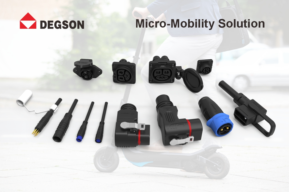
| Architecture | Recommended DEGSON series | Current class | Signal channel | Typical use case |
|---|---|---|---|---|
| Same-port (shared charge + discharge) | EBBH 80A / EBBH 120A | 80A continuous / 120A (per model) | Integrated 2A signal (EBBH 80A) | Fixed-battery vehicles, tight space, BMS interlock available |
| Separate-port (discharge) | EBBH 80A / EBBH 120A | 80A continuous / 120A (per model) | Integrated 2A signal (EBBH 80A) | Removable-battery vehicles charging off-board |
| Separate-port (charging inlet) | EBC / EBSC | Per model (datasheet) | N/A | Dedicated charging port on vehicle or charger adapter |
| Signal harness at battery interface | EBI | Signal only | Multi-pole | Pre-assembled labeled harness for port wiring |
Why Some E-Motorcycles Share One Port for Charging and Discharging
The architecture decision:
In a separate-port architecture, the battery has one connector for the discharge path (to motor and controller) and another connector for the charge path (from charger). This is common on removable-battery vehicles that charge off-board. In a same-port architecture, the battery uses a single connector for both directions — the charger plugs into the same port that normally carries discharge current. This is common on fixed-battery vehicles and on vehicles where the battery is not easily removed.
Why choose same-port:
The same-port approach reduces connector count, saves battery compartment space, shortens the wiring harness, and lowers cost. It also simplifies the user experience — the rider plugs the charger into the same visible port every time, which reduces wrong-port errors in the field. The trade-off is that the single connector must now carry both charge and discharge currents, and the system must positively prevent the charger from being misconnected to the discharge circuit or the battery polarity from being reversed.
How DEGSON addresses it:
For a shared charge-discharge interface, the DEGSON EBBH series is positioned as the battery-side port. The EBBH 80A model integrates an 80A continuous power channel with a 2A signal channel, is rated IP67 for both mated and unmated conditions, operates over -40C to +105C, specifies a mechanical life of no less than 3000 mating cycles, an extraction force above 50N, and a UL 94 V-0 rated housing (confirm the exact values for the target part number in the datasheet). The EBBH 120A model provides a higher current class for more powerful e-motorcycles. The integrated 2A signal channel lets the BMS communicate over the same connector, supporting port-state monitoring and interlock logic. For vehicles that keep charging separate, the DEGSON EBC (flap-cover charging inlet) and EBSC (charging plug and receptacle) series serve as dedicated charging ports.
Reverse-Connection and Wrong-Plugging Protection: Keying, Pin Assignment and BMS-Linked Protection
The hazard:
On a shared port, the charger cable and the battery discharge cable may use similar connectors. If a charger is plugged into the discharge path, or if the battery terminals are reversed when the battery is reinstalled, the resulting polarity error or circuit misconnection can damage the BMS, blow fuses, melt wiring, or start a fire. Because the same port handles both directions, the safety margin is lower than in a separate-port design, where the charge and discharge paths are physically isolated.
Protection layers:
Four layers are commonly used together. First, mechanical keying: the housing shape and pin layout physically prevent the charger connector from mating with the discharge socket, or prevent reverse insertion. Second, pin assignment: power and signal pins are arranged so that polarity reversal is impossible without forcing the connector. Third, ground-first mating: ground pins make contact before power pins, providing a safe reference before current flows. Fourth, BMS-linked protection: the BMS monitors the port state (through the integrated signal channel) and can open the power path before damage occurs if a wrong connection is detected. Verify the keying and pin layout of the selected connector model in its datasheet drawing.
How DEGSON addresses it:
DEGSON battery and charging connectors use polarized housings and defined pin assignments to prevent reverse insertion; the EBBH series integrates a signal channel so the BMS can monitor port state, and the EBBF swapping connector demonstrates keyed, float-compensated blind mating. Confirm the keying scheme and pin layout for the specific part number in its datasheet, and coordinate with your BMS vendor on the interlock logic — the connector alone does not replace the protection circuit.
Current Rating and Pin Sizing for Bidirectional Current Flow
The sizing rule:
A shared-port connector carries current in both directions: discharge current (battery to motor, typically the higher of the two) and charge current (charger to battery). The connector and its terminals must be rated for the larger of the two currents, with margin. Charge current is often lower than peak discharge current, but charging is a sustained operation — hours of continuous current — so temperature rise at the charge current must also be checked, not just the peak discharge rating.
What to verify:
When sizing a shared-port connector, verify from the datasheet: the continuous current rating (not just peak), the temperature rise specification at both charge and discharge current levels, the terminal contact resistance (with measurement conditions), and the wire size range supported by the terminals. For the DEGSON EBBH 80A, the 80A rating is a continuous rating with the operating temperature range -40C to +105C — confirm the derated current at your actual ambient temperature and the recommended wire gauge from the datasheet. For fast-charging vehicles where charge current approaches discharge current, the connector must be sized for the worst case of the two.
How DEGSON addresses it:
The DEGSON EBBH series provides two current classes — the EBBH 80A (80A continuous power + 2A signal, IP67 mated and unmated, -40C to +105C, >=3000 cycles, extraction force >50N, UL 94 V-0 housing) and the EBBH 120A (120A class, confirm exact values per part number). Temperature rise, contact resistance and wire size range are listed per model in the datasheet. DEGSON can support the current-capacity review for a shared-port design based on the vehicle charge and discharge profiles.
Same-Port vs. Separate-Port: Architecture Trade-Offs
The comparison:
Same-port saves space, parts and wiring, and gives the rider one obvious charging port — but it concentrates both high-current paths in one connector and requires active protection logic. Separate-port isolates the charge and discharge paths electrically, which is inherently safer and simpler to protect, but costs an extra connector, more wiring, and a second port on the vehicle body. The right choice depends on the battery architecture (removable vs. fixed), the charge current relative to discharge current, and the safety logic budget.
Selection guidance:
Removable-battery vehicles that charge off-board: keep the ports separate — discharge through the EBBH series battery connector, charging through a dedicated inlet (EBC or EBSC). Fixed-battery vehicles where space is tight and the BMS has interlock capability: a shared port built on the EBBH series (power plus signal) is a viable, space-efficient option, provided the protection layers above are implemented. If charge and discharge currents differ significantly, separate connectors may be more efficient than oversizing a single shared connector. Refer to the architecture comparison table above for the series mapping.
How DEGSON addresses it:
DEGSON supports both architectures with different series: EBBH for shared or discharge interfaces with integrated signal, EBC/EBSC for dedicated charging inlets on separate-port vehicles. Map the architecture first, then select the series — confirm ratings, pin count and interface role per part number in the datasheet before final selection.
Wiring Layout and Ground-First Mating for the Shared Port
The wiring concern:
A shared charge-discharge port concentrates the battery positive, battery negative, and BMS signal wires at one location. Wiring errors here are high-consequence — a crossed wire can short the battery through the charger or the controller. The harness must be built to the defined pin map, with color-coded or labeled wires, and validated before production.
Design practices:
Define a single pin map for the shared port and print it on the harness drawing; make ground (or negative) pins mate first and break last so a safe reference exists before power contacts engage; keep the BMS signal wires separate from the power wires inside the connector to avoid noise coupling; and for blind mating (fixed-battery vehicles where the rider cannot see the port), rely on keyed housings and guidance features rather than visual alignment.
How DEGSON addresses it:
The DEGSON EBBH series pin layout is defined per part number in the datasheet, supporting ground-first and power-signal separation design. The DEGSON EBI series signal wire harness solutions provide pre-assembled, labeled harnesses for the battery interface, reducing field wiring errors on a safety-critical port. Confirm the pin layout of the selected part number in the datasheet and validate the harness against the pin map before production.
Three Checks for a Charge-Discharge Shared Port
1. Verify mechanical protection: keying and pin layout that physically prevent reverse insertion and charger-to-discharge misconnection — confirm in the datasheet drawing.
2. Check current sizing for both directions: continuous rating and temperature rise at the higher of charge/discharge current, with margin, from the datasheet — for EBBH 80A, 80A continuous at -40C to +105C operating range, derate to your actual ambient.
3. Confirm the BMS interlock: the connector must provide a signal channel (EBBH 80A: 2A signal) so the BMS can monitor port state and interrupt current before damage — the connector is one layer, the protection circuit is the other.
Five Recurring Charge-Discharge Same-Port Mistakes
-
Assuming the discharge rating covers the charge case — sustained charging temperature rise is ignored.
-
No keying or pin layout review — a charger can physically fit the discharge socket.
-
No BMS interlock — the port state is not monitored and a wrong connection is not caught.
-
Signal and power pins intermingled — BMS communication is corrupted by power noise.
-
Crossed harness wires on the shared port — battery shorted through charger or controller.
FAQ
Q1: What current rating does a charge-discharge shared port need?
A: The shared port must be rated for the larger of the charge and discharge currents, with margin, and must also be checked for sustained temperature rise because charging is a continuous operation lasting hours. The DEGSON EBBH 80A provides an 80A continuous power channel plus a 2A signal channel, operates over -40C to +105C, and is rated IP67 for both mated and unmated conditions; the EBBH 120A provides a higher current class. Confirm the continuous current rating, temperature rise and contact resistance of the target part number in its datasheet, and size for the worst case of charge vs. discharge at your actual ambient temperature.
Q2: How does a charge-discharge shared port prevent reverse connection?
A: Through four layers used together: mechanical keying and pin layout that physically prevent reverse insertion or charger-to-discharge misconnection; pin assignment that makes polarity reversal impossible without forcing the connector; ground-first mating that establishes a safe reference before power contacts engage; and BMS-linked protection that monitors port state through an integrated signal channel and interrupts current before damage. DEGSON EBBH integrates a power channel with a 2A signal channel for BMS monitoring, and uses polarized housings. Confirm the keying scheme and pin layout for the specific part number in its datasheet.
Q3: Should my vehicle use a shared charge-discharge port or separate ports?
A: Use a same-port architecture when space is limited and the BMS can supervise the port state; use separate ports when off-board charging, simpler protection logic or easier certification review is the priority. Removable-battery vehicles that charge off-board should keep ports separate — discharge through the DEGSON EBBH series battery connector, charging through a dedicated inlet (DEGSON EBC flap-cover inlet or EBSC plug/receptacle). Fixed-battery vehicles with tight space and BMS interlock capability can use a shared port on the EBBH series (power plus signal). See the architecture comparison table in this article for the series mapping.
Q4: How many mating cycles does a shared charge-discharge port need?
A: The port is mated every time the vehicle is charged, so the mechanical life must cover the design-life number of charging events, not the daily ride cycle. The DEGSON EBBH 80A specifies a mechanical life of no less than 3000 mating cycles and an extraction force above 50N (confirm the exact value for the target part number). For shared ports on fixed-battery vehicles, also verify that the connector withstands repeated blind mating without pin damage — keyed housings and guidance features support this. Check the mechanical life and extraction force specifications in the datasheet.
Q5: How should the shared-port wiring be laid out to avoid errors?
A: Define a single pin map for the shared port and print it on the harness drawing; make ground (or negative) pins mate first and break last; keep BMS signal wires separate from power wires inside the connector; and use keyed housings and guidance features for blind mating on fixed-battery vehicles. The DEGSON EBI series signal wire harness solutions provide pre-assembled, labeled harnesses for the battery interface, reducing field wiring errors. Validate the harness against the pin map before production, and confirm the pin layout of the selected part number in its datasheet.
References
References used in this article are grouped by type to avoid confusion between company-level management systems, material standards, product safety standards and product datasheets:
-
Product safety standard: UL 4128 — applies only where a connector safety standard is explicitly claimed for a specific DEGSON series or model in its datasheet; do not treat it as a series-wide certification unless the datasheet states it.
-
Material standard: UL 94 — the DEGSON EBBH series housing material is rated UL 94 V-0 as stated in the product datasheet (confirm per part number); other series apply only where the specific model housing is confirmed as V-0.
-
Company-level quality system: IATF 16949 — a company management system reference; unless explicitly stated in a product datasheet, it should not be interpreted as a product certification for a specific connector series or model.
-
Product data: DEGSON micro-mobility connector product datasheets and drawings — the authoritative source for current ratings, pin layouts, IP ratings, mating cycle ratings, extraction force, operating temperature and dimensions.
Next Step
Before finalizing a charge-discharge shared port, review the DEGSON product page and datasheet for the EBBH part number used in your design, and confirm the current rating, pin layout, keying, IP rating, mating cycle rating and temperature specifications. For separate-port architectures, verify the EBC or EBSC charging inlet rating. Coordinate the BMS interlock logic with your BMS vendor — the connector is one layer of safety, the protection circuit is the other. Contact the DEGSON engineering team for current-capacity review and custom pin assignment support.


