Why Reflow-Solderable PCB Terminal Blocks Are Increasingly Chosen: A THR Switching Guide for Equipment Manufacturers
At DEGSON, we see an increasing number of equipment manufacturers moving their PCB terminal blocks from wave soldering to reflow soldering. The driver is that SMT lines are converging on a single "solder-once" process. Through-hole reflow (THR) terminals are placed by the pick-and-place machine and soldered in the same reflow pass as the other SMD components, eliminating the separate wave-soldering or manual touch-up step. This reduces labor, work-in-process and tooling while making solder joints more consistent. However, a standard terminal block is not built to survive reflow temperatures, and sending one through the oven will soften or deform it. This guide explains why THR is becoming standard, where it fits, how to select it, and presents the DEGSON DG246-THR solution.
1. Why THR terminal blocks are becoming the equipment maker's choice
Conventional through-hole components are soldered by wave after SMT placement, or touched up by hand. This is a separate process, sensitive to flux and spray uniformity, and prone to bridging, skips and cold joints. The more automated the line, the more this "insertion-and-wave" step becomes a takt-time bottleneck.
THR brings the through-hole terminal into the SMT flow: the pick-and-place machine feeds and seats it, and it is reflowed in one pass with the resistors, capacitors and ICs. The board follows a single soldering line, labor and waiting time fall, and joints are more repeatable. This is the fundamental reason reflow-solderable PCB terminal blocks are increasingly chosen in equipment manufacturing.
2. Reflow, wave and manual soldering compared
The difference between the three processes is essentially whether the through-hole part is merged into the SMT main line. Before selecting, compare your own line against the table below.
Table 1 — Comparison of the three soldering processes
| Process | Merged into SMT line | Terminal heat resistance | Joint consistency | Labor |
|---|---|---|---|---|
| Reflow THR | One pass in the same oven | High (survives above 235 °C) | High | Low |
| Wave | Separate pass | Lower | Medium | Medium |
| Manual | Point-by-point touch-up | Low | Operator dependent | High |
3. Two gates before a terminal goes through reflow
Whether a terminal survives reflow starts with material. Lead-free reflow peak temperatures are typically above 235 °C (often 235–250 °C). A wave-soldering housing will soften, blister or shift its pins at these temperatures. A THR terminal must use high-temperature insulation (such as a UL94 V0 housing), pass the glow-wire test, and have its contacts and retainers designed for the reflow thermal mass.
The second gate is board-level design. The PCB hole must match the pin, while stencil thickness and solder-paste volume must guarantee hole fill. High-thermal-mass terminals need more paste and a tuned oven profile, and current may need to be derated; otherwise insufficient hole fill, tombstones or cold joints appear. This is why a general-purpose PCB terminal must never be used as a reflow-rated part.
4. Which products should switch, and which need evaluation first
The payoff is greatest for highly automated, low-hole-count, consistent-takt boards — such as inverter control boards, smart meters, PLCs and sensors. High-current, high-thermal-mass or densely perforated terminals should first go through first-article and thermal-mass evaluation. Feeding also matters: tape-and-reel (Reel) goes straight into the SMT feeder for the highest automation, while tube and bulk packaging require manual or semi-automatic support.
5. THR terminal selection checklist
Selecting a THR terminal is not only about the part itself; its parameters must match the line's capability. The table below can be checked point by point.
Table 2 — THR terminal selection checklist
| Selection dimension | What to check |
|---|---|
| Pitch and number of ways | Match PCB layout and circuit count; keep pad clearance and creepage distance |
| Rated current / voltage | Select by actual load and system voltage; keep a current-derating margin |
| Connection method | Fixed push-in for tool-free wiring; pluggable for quick module separation |
| Feeding method | Tape-and-reel for high-automation SMT; tube or bulk for low volume |
| Housing material | High-temperature, UL94 V0 flame-retardant, glow-wire tested |
| Pin and PCB hole | Pin diameter matches the PCB hole; ensure hole fill and joint strength |
| Soldering compatibility | Explicitly marked THR; confirm whether wave/manual soldering is also supported |
6. Application and switching guidance
From industrial automation and new energy to intelligent buildings, equipment production keeps moving toward higher automation and fewer manual steps; reflow-solderable PCB terminal blocks are the connection-level expression of that trend. Before switching, it is advisable to use the connector layout, the number of through-hole joints and the actual oven profile to complete first-article trials plus hole-fill and thermal-mass evaluation, and only then ramp to volume — so the efficiency and consistency of one-pass THR soldering can be fully captured.
7. DEGSON reflow-solderable PCB terminal solution
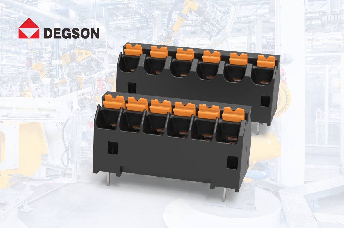
The DEGSON DG246-THR series is a PCB-mounted PUSH-IN spring terminal block with a 45° wire entry, straight in-line pins, 2-8 poles, a black housing and tin-plated contacts. It uses a high-temperature UL94 V0 housing that passes the glow-wire test, so it can be through-hole reflow soldered in the same pass as the SMD components, and it also supports wave and manual soldering. Solid wires and ferruled flexible wires are inserted directly without tools, suiting compact, highly automated equipment such as inverter drives, smart meters, PLCs and sensors.
Table 3 - DEGSON DG246-THR series selection
| Model | Pitch | Nominal current | Rated voltage (III/2) | Wire range | Soldering |
|---|---|---|---|---|---|
| DG246-THR-3.81 | 3.81 mm | 17.5 A | 160 V | 0.2-1.5 mm² | Reflow/wave/manual |
| DG246-THR-5.08 | 5.08 mm | 17.5 A | 320 V | 0.2-1.5 mm² | Reflow/wave/manual |
Select the pitch by circuit voltage (3.81 mm for 160 V, 5.08 mm for 320 V); fine stranded wires should be ferruled, and the wire range is up to 1.5 mm². The exact ratings, derating curves and packaging (tape/tube) are given in the applicable DG246-THR datasheet.
Q&A
Q1. Can I run a standard terminal block through reflow? No. A standard or wave-soldering housing is not rated for the peak above 235 °C and may soften or blister. Only a terminal explicitly marked THR, with a high-temperature V0 housing and a verified reflow profile, should be used.
Q2. What peak temperature should the terminal be designed for? Lead-free reflow peaks are typically above 235 °C (often 235–250 °C, in line with IEC 61760). Confirm the terminal's THR rating on its datasheet and qualify it against your own oven profile, rather than assuming a temperature from the shop floor.
Q3. Can high-current, large terminals use reflow? Yes, but with evaluation. A high thermal mass makes hole fill harder. Verify paste volume, stencil opening, preheat and the joint cross-section on first articles, and apply current derating where required.
Q4. Tape-and-reel, tube or bulk — which feeding method? Tape-and-reel is the most automated and goes directly into the pick-and-place feeder; tube and bulk require manual or semi-automatic loading. Choose reel for high-volume SMT lines and the others for low-volume or non-tapable models.
Q5. If I switch to THR, do I still need wave soldering? For the terminals converted to THR, no separate wave step is needed for those joints — they are soldered with the SMDs in one pass. Any remaining through-hole parts that are not THR still require wave or manual soldering, so review the full BOM before removing the wave line.
Q6. Does DEGSON offer a terminal block that can go through reflow? Yes. The DEGSON DG246-THR series is a PUSH-IN spring PCB terminal with a high-temperature V0 housing and tin-plated contacts, through-hole reflow soldered in the same pass as the SMDs (2-8 poles, 3.81/5.08 mm pitch, 17.5 A), and it also supports wave and manual soldering. See the DG246-THR datasheet on the DEGSON website and request samples for validation.
References
[1] Illes B., Krammer O., Geczy A. Reflow Soldering: Apparatus and Heat Transfer Processes [M]. Elsevier, 2020. ISBN 978-0-12-818505-6.
[2] Jia Zhongzhong. SMT Core Process Analysis and Case Studies (3rd ed.) [M]. Beijing: Publishing House of Electronics Industry, 2016. ISBN 978-7-121-27916-4.
[3] Yu Guoxing (ed.). Fundamentals of Modern Electronic Assembly Processes [M]. Xi'an: Xidian University Press, 2007. ISBN 978-7-5606-1815-9.
[4] IEC 61760-1 Surface mounting technology - Part 1: Standard method for the specification of surface mounting components (SMDs); IEC TR 61760-3-1:2022 Standard method for the specification of components for through-hole reflow (THR) soldering - Guidelines for through-hole diameter design with solder paste surface printing.
[5] IPC J-STD-001 Requirements for Soldered Electrical and Electronic Assemblies; IPC-A-610 Acceptability of Electronic Assemblies.
[6] IEC 60695-2-11 Glow-wire end-product flammability test (GWEPT); UL 94 Tests for Flammability of Plastic Materials for Parts in Devices and Appliances.
[7] DEGSON. DG246-THR Series Reflow Soldering Compact Mini Terminal Blocks [EB/OL]. DEGSON, 2026-07-09. www.degson.com
Source: DEGSON official website, www.degson.com


