Connector Mating Life and Contact Plating Selection: A Gold, Silver and Tin Guide
At DEGSON, contact plating selection is driven by four factors: the circuit type, the number of mating cycles, the vibration environment, and the validated mating pair. Across DEGSON pluggable and PCB terminal blocks, DIN-rail terminal blocks, circular connectors and heavy-duty connectors, interfaces carrying low-level signals, frequent mating or vibration are generally gold plated, while tin is the standard finish for general power and control circuits, and silver is used for high-current and high-frequency interfaces. The plating is only a few micrometres thick, yet it determines contact resistance, wear, corrosion and fretting behaviour, and the dearest finish is not always the best. This guide explains the wear mechanism, typical thickness and life ranges, and maps each finish to the relevant DEGSON product series, with standards, test references and a bibliography.
1. Plating mainly solves the mating-interface problem
A contact is usually made from a copper alloy such as brass or phosphor bronze, with a very thin metal layer on top. It has two working zones: the crimp zone where the conductor is terminated, and the mating zone where it meets the opposing contact. The crimp zone is about conductor compression, mechanical retention and pull-off force, governed mainly by crimp geometry. The mating zone is a separable interface, concerned with contact resistance, wear, vibration fretting and corrosion.
Plating selection primarily addresses the mating zone and only indirectly affects crimp pull-off force; switching to a more expensive finish cannot be expected to raise crimp strength. The same contact may also be selectively plated, for example gold in the mating zone and tin in the termination zone, so "gold-plated terminal" does not mean every area has the same surface. On DEGSON pluggable PCB terminal blocks the contacts are copper alloys: the standard 15EDGK/2EDGK plugs are tin plated in the wire-entry area with a nickel underplate, and the 15EDGKAM-3.81 datasheet specifies a copper-alloy contact with nickel plating on the contact point and tin plating in the wire-entry area; some sockets such as the 9EDGRC-5.0 use a gold-plated contact surface for higher-reliability signal use.
2. Comparison of the four plating materials
Table 1 Comparison of gold, silver, tin and nickel plating
| Plating | Contact resistance | Wear / mating | Corrosion | Typical use | Cost |
|---|---|---|---|---|---|
| Gold Au | Low and stable | Hard gold resists wear, long life | Best (noble, no oxide) | Low-level signals, data, sensors, frequent mating | High |
| Silver Ag | Lowest initially | Moderate | Good, but tarnishes with sulfur | High-current power, high frequency, busbars/lugs | Medium-high |
| Tin Sn | Medium initially, rises over time | Soft, wears under frequent mating | Adequate for normal humidity | General power and control, fixed installation | Low |
| Nickel Ni | Hard film | High (often underplate) | Good | Barrier/underplate, rarely the top finish | Low |
Gold is a noble metal that does not oxidize and keeps contact resistance stable; hard gold (alloyed gold) is hard and wear-resistant, making it the first choice for low-level signals and frequent mating. Tin is low cost, easy to solder and crimp, and is the mainstream finish for general industrial connectors. Silver offers the best conductivity and high-temperature tolerance for high current but tarnishes with sulfur. Nickel mainly serves as a barrier layer beneath the top finish, preventing copper diffusion and improving wear.
3. Mating life, plating thickness and the governing standards
Mating life is determined by plating thickness, hardness, contact normal force and the terminal design. A thicker, harder plating withstands repeated rubbing; a higher normal force lowers contact resistance but accelerates wear. The table below gives industry-common thickness and life ranges for reference; they are general ranges, not product ratings. For DEGSON products, plating, mating life and contact resistance are assessed under the relevant product standards: terminal blocks use IEC 61984 (connectors, safety requirements and tests) and UL 1059 (standard for terminal blocks), while connector test methods reference IEC 60512 and the EIA-364 series (e.g. EIA-364-09 durability, EIA-364-06 contact resistance). The actual values for each series are given in its datasheet and take precedence over the general ranges in Table 2.
Table 2 Plating thickness and typical mating-life reference (general ranges, not product ratings)
| Plating / type | Typical thickness | Reference mating life | Application |
|---|---|---|---|
| Tin (matte) | ~2-5 µm | Few matings, order of 10-30 cycles | Fixed/rare mating, general power |
| Silver | ~2-5 µm | ~100-200 cycles | High current, periodic maintenance |
| Flash gold | ~0.025-0.1 µm | ~50-100 cycles | Infrequent mating, surface protection |
| Hard/heavy gold (Ni underplate) | ~0.5-1.5 µm | ~500-1000 cycles | Frequent mating, long life |
Note that flash gold is mainly for surface protection; under frequent mating it quickly wears through to the underlayer and must not be used at heavy-gold life. Gold is usually applied over a nickel underplate, which both blocks copper diffusion into the gold and provides mechanical support. Overall, plating has little effect on the total current-carrying capacity of the conductor; interface condition, normal force and the mating material determine contact performance.
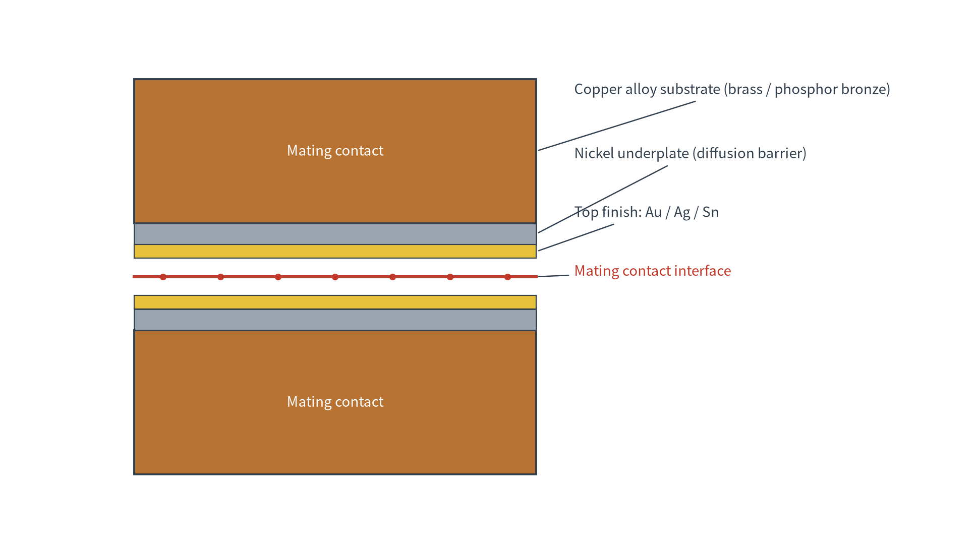
Figure 1 Cross-section of a plated contact: top finish, nickel underplate and copper-alloy substrate
4. Fretting corrosion: a contact-resistance risk under vibration
In vibrating systems such as engines, pumps, robots, servo drives and vehicles, the contact interface undergoes micrometre-scale relative movement called fretting. As the surface film is broken, fresh metal is exposed and rapidly oxidizes, and oxide debris accumulates; even though the connector remains mechanically locked, contact resistance grows and becomes unstable over cycles.
Tin is the most sensitive to fretting corrosion because it is soft and oxidizes quickly, especially in low-level signal circuits. Gold, being a noble metal that does not oxidize, resists fretting well. Tin fretting can be mitigated with matte tin, a higher and stable normal force, and contact lubricants. Therefore interfaces that operate under continuous vibration with very small signal currents, such as the signal pins in high-protection circular servo connectors, are better suited to gold.
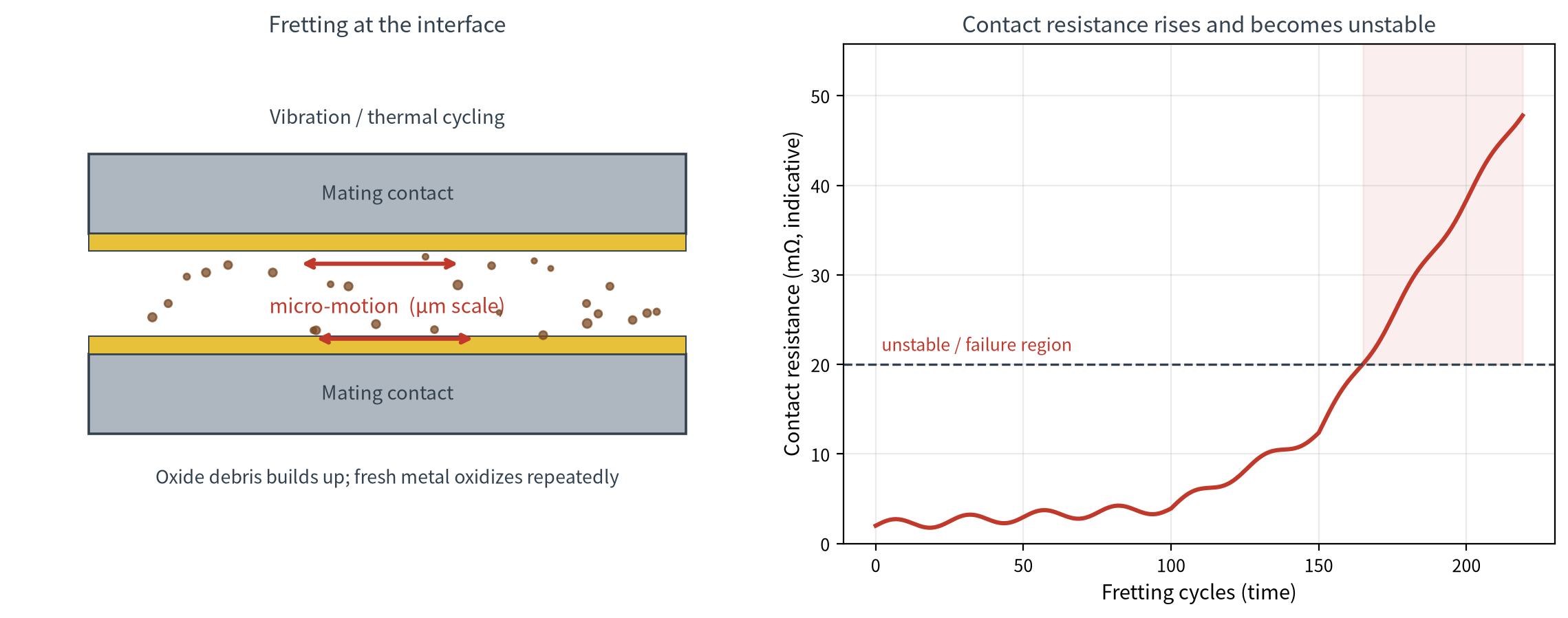
Figure 2 Fretting corrosion mechanism and contact-resistance drift over cycles
5. Tin-plating salt-spray resistance and natural-aging correlation
The neutral salt spray (NSS) test is the most common accelerated corrosion test for connectors, conducted per GB/T 10125-2021 (MOD ISO 9227:2017) or ASTM B117: the chamber is held at 35 °C, continuously atomizing 5% sodium chloride at close to 100% relative humidity. It is important to note that there is no internationally standardized conversion between salt-spray hours and natural aging. The chamber only amplifies the single condition of high salt and high humidity and lacks UV, wet-dry cycling, rain wash-off and industrial gases. Salt-spray hours therefore cannot be equated directly with service years, cannot be linearly extrapolated (for example, 480 h cannot be taken to mean 100 years), and must not be written into a warranty. Table 4 gives empirical ranges compiled from testing and test-equipment industry sources, for preliminary selection only.
Table 4 NSS duration and natural-aging correlation (by environment, empirical ranges, not product ratings)
| NSS duration | Mild / indoor, sheltered | General outdoor, industrial | Coastal / road salt, severe |
|---|---|---|---|
| 24 h | ~0.5-1 year | ~4-8 months | ~1-3 months |
| 48 h | ~1-2 years | ~0.8-1.5 year | ~3-6 months |
| 96 h | ~2-4 years | ~1.5-3 years | ~1-2 years |
| 240 h | ~5-8 years | ~3-5 years | ~2-3 years |
| 480 h | ~8-12 years | ~5-8 years | ~3-5 years |
| 1000 h | ~10+ years | ~8-10 years | ~5-10 years |
How many salt-spray hours a tin layer can pass depends mainly on its thickness, density (porosity) and whether a nickel underplate is present. A thicker, less porous tin layer lasts longer in salt spray, and the nickel underplate acts as a diffusion barrier, preventing corrosive media from reaching the copper substrate through pores in the plating, which is key to raising the salt-spray grade. Tin-plated general industrial connectors (~2-5 µm with nickel underplate) commonly use a 24-48 h acceptance threshold with no significant corrosion; automotive and high-reliability applications often require 96 h, and marine/coastal applications require more. Thin tin, no nickel underplate or high porosity tends to show oxidation spots first at the pores. In practice, first define the actual operating environment (indoor / general outdoor / coastal), use Table 4 to determine the required salt-spray grade, and then specify the tin thickness and nickel underplate. The exact hours and acceptance criteria are governed by the product standard and actual testing; for high-reliability applications, cyclic corrosion testing (CCT) and outdoor exposure testing are recommended.
6. A five-step plating selection and the DEGSON series mapping
First, classify the circuit: high-current power circuits focus on heating and current stability, while low-level signal circuits are most sensitive to surface films. Second, consider mating cycles and vibration: frequently mated or vibrating interfaces focus on wear and fretting. Third, consider the environment: humidity, salt spray, sulfur-bearing atmospheres and operating temperature all affect the finish. Fourth, consider the mating pair: prefer the mating finish specified or validated by the manufacturer. Fifth, compare cost and supply, selecting for reliability first.
Without special requirements, tin is the default for general power and control; gold is only upgraded to when the circuit is a small signal, mating is frequent, or the environment clearly requires it; silver is considered for high current and high frequency. Even for high current, silver should not be chosen solely because "silver conducts well"; the terminal structure, allowable temperature rise and ratings must also be considered. Table 3 maps these rules to DEGSON series.
Table 3 DEGSON product series with typical contact plating and test basis
| DEGSON series / representative | Typical contact plating | Typical application | Mating life / test basis |
|---|---|---|---|
| Pluggable PCB plug 15EDGK/2EDGK (e.g. 15EDGKAM-3.81, 7A/250V class) | Copper alloy, nickel underplate, tin in wire-entry | General power and control, low-to-mid mating | Per datasheet; mechanical tests to IEC 61984 / UL 1059 |
| Pluggable PCB socket gold version (9EDGRC-5.0, 16A class) | Copper alloy, gold-plated contact surface | Low-level signals, frequent mating, high reliability | Per datasheet; IEC 61984 / UL 1059 |
| Test/measurement terminals (phosphor-bronze contacts) | Per series | Test points, maintenance, repeated mating | Per DEGSON literature, passed 10,000 mating cycles |
| Circular M-series / servo connectors (M23, IP67) | Per series, signal pins often gold | High-vibration, high-protection servo and motors | Per datasheet; per series standard |
| Energy-storage / heavy-duty high-power connectors | Tin or silver per series | High-current power, 50A and above | Per datasheet; IEC 61984 / UL 1059 |
The plating and life in Table 3 represent typical configurations only. The exact plating option, thickness, rated mating cycles and contact resistance vary by part number and are given in the applicable DEGSON datasheet; the same part number may offer tin or gold ordering options, so the order code should be checked during selection.
7. Mating pairs and common pitfalls
The finishes on both mating halves are generally kept the same. Dissimilar metal pairing can cause galvanic corrosion or change wear behaviour through hardness mismatch; gold-tin mixing causes gold transfer and cold welding, and most manufacturers require specific validation for gold-tin pairs. If mixing is unavoidable, follow the manufacturer's validated results. Common pitfalls include assuming gold is always best (it is wasteful for high current), that tarnished silver has failed (silver sulfide can still conduct under contact pressure), that tin means low end (it is mainstream when matched), using flash gold as heavy gold, and failing to re-validate after changing the finish.
Changing the finish, material or supplier should be treated as a process change: re-confirm contact dimensions, plating and underplate, crimp height, crimp cross-section, pull-off force and contact resistance, and where necessary add durability, vibration, temperature-rise and salt-spray environmental tests before mass production.
Frequently asked questions (Q&A)
Q1: Why is tin not recommended for low-level signal circuits?
Low-level signals (millivolt, milliamp) are most sensitive to surface films. Under long-term oxidation and vibration fretting, tin's contact resistance grows and becomes unstable, causing intermittent faults. Gold does not oxidize and resists fretting, maintaining low, stable contact resistance over time, making it better suited to signal and data circuits.
Q2: Why do high-current terminals often use silver?
Silver offers the best conductivity and initial contact resistance and high-temperature tolerance, suiting power circuits, busbars and lugs above 50-200A. It tarnishes with sulfur, however, so storage, packaging and pairing design must be strengthened, and current capacity still depends on the terminal structure and allowable temperature rise.
Q3: Can a blackened silver terminal still be used?
Silver forms silver sulfide and discolors in sulfur-bearing environments; color alone is not a valid criterion. Light tarnish can still conduct under sufficient contact normal force, and the effect is usually small in high-current, high-force circuits; low-level signal circuits are more sensitive to surface films. Significant discoloration should be isolated and checked against the datasheet or with the supplier.
Q4: Is thicker gold always better?
Frequent mating and long-life applications need heavy gold (~0.5-1.5 µm, nickel underplate); but excessive gold on a solderable area causes gold embrittlement, and infrequently mated interfaces only need flash gold. The key is to select by mating cycles, solderability and cost, not to thicken blindly.
Q5: Which DEGSON product should be chosen for frequent mating or low-level signals?
Signal, data or high-frequency mating interfaces should use gold-plated contacts, such as the gold-contact-surface 9EDGRC-5.0 pluggable PCB socket, rather than the tin-standard 15EDGK/2EDGK plugs used for general power and control; high-current power uses the specified tin or silver options in the energy-storage or heavy-duty series. In every case, confirm the plating option, rated mating cycles, contact-resistance limits and test standard in the applicable DEGSON datasheet, and mate the two halves as specified.
8. Selecting and verifying with DEGSON
The plating options, rated mating cycles, contact-resistance limits, ambient-temperature range and application boundaries of each DEGSON series are listed on its product page and datasheet, with the corresponding IEC, UL and VDE certifications. Because plating interacts with contact normal force, contact geometry and the mating pair, for signal, high-frequency mating or vibration interfaces DEGSON recommends confirming the plating solution and requesting samples for validation before mass production. The plating options, rated mating cycles and application boundaries of each series can be found on the relevant DEGSON product pages and datasheets.
References
[1] Liu Renzhi. Electronic Electroplating Technology (2nd ed.) [M]. Beijing: Chemical Industry Press, 2023. ISBN 978-7-122-42597-3. (Includes chapters on electronic connector plating and printed circuit board plating.)
[2] Wang Yue, Feng Liming (eds.). Electroplating Technology (2nd ed.) [M]. Beijing: Chemical Industry Press, 2018. ISBN 978-7-122-32718-5. (Higher-education "13th Five-Year" textbook.)
[3] Miao Jingguo (ed.). Metal Surface Treatment Technology (2nd ed.) [M]. Beijing: China Machine Press, 2023. ISBN 978-7-111-73749-0.
[4] GB/T 10125-2021 Corrosion tests in artificial atmospheres - Salt spray tests (MOD ISO 9227:2017); ASTM B117 Standard Practice for Operating Salt Spray (Fog) Apparatus.
[5] GB/T 6461-2002 Methods for corrosion testing of metallic and other inorganic coatings on metallic substrates - Rating of test specimens and manufactured articles subjected to corrosion tests (IDT ISO 10289:1999).
[6] IEC 60068-2-11:2021 Environmental testing - Part 2-11: Tests - Test Ka: Salt mist; EIA-364-26 Salt Spray Test Procedure for Electrical Connectors, Contacts and Sockets (EIA-364-26C, 2014, R2019; references IEC 60512-11-6).
[7] IEC 61984:2008 Connectors - Safety requirements and tests (incl. COR1:2011);
Source: DEGSON official website, www.degson.com


