SCCR in UL 508A Control Panels (2026): How Terminal Block Selection Sets the Panel Ceiling
Applicable to: industrial control panels built to UL 508A for North American markets, and the power-circuit components inside them — DIN-rail terminal blocks, fuse terminal blocks, PCB and pluggable connectors — evaluated per NEC Article 409 and UL 508A Supplement SB.
Not applicable to: panels containing only control circuit components, exempt from SCCR marking under NEC Article 409; equipment outside NEC jurisdiction, where IEC 61439 and IEC 60947 ratings apply instead; and components whose short-circuit withstand is evaluated only inside a finished-product listing, with no separately published component SCCR.
SCCR is defined at two levels, and conflating them is the first source of error. At component level it is the maximum prospective fault current an individual device — fuse, breaker, terminal block, contactor, motor starter, transformer — can withstand without damage exceeding defined acceptance criteria. At assembly level it is the maximum available fault current the complete panel may be connected to. NEC Article 100 gives the formal wording: the prospective symmetrical fault current at a nominal voltage to which an apparatus or system can be connected without sustaining damage exceeding defined acceptance criteria.
The consequence is arithmetic rather than engineering judgment. If the 480 VAC feeder can deliver 100 kA of available fault current, every power-circuit component in the panel must withstand it — and the assembly is rated at whatever the lowest-rated component among them can take. A panel calculated at 10 kA is non-compliant on a 100 kA feeder no matter how highly rated the fuses ahead of it are.
Two properties of the number are easy to lose. It is voltage-dependent — a rating established at 240 V does not transfer to 480 V, because higher voltage sustains a longer arc and that additional energy is what destroys the device. And it is installation-dependent: SCCR is only meaningful against the available fault current at the point of installation, so a panel compliant on a 25 kA service is not automatically compliant after the utility or facility distribution changes.
SCCR marking on industrial control panels entered the National Electrical Code with the 2005 edition; adoption dates differ by state, since each jurisdiction adopts its own NEC edition on its own schedule. Article 409 covers installation of industrial control panels at and under 1000 volts, and an informational note in Article 409 references UL 508A Supplement SB4 as an approved calculation method (Rockwell Automation, SCCR-AT002).
The provisions that govern a panel build:
409.110(4) — the panel label must state the SCCR, established either by a listed and labeled assembly or by an approved method such as UL 508A Supplement SB.
409.22 — a panel shall not be installed where the available fault current exceeds its marked SCCR. Recent editions add a requirement to document that available fault current and the date of the calculation.
110.9 — overcurrent protective devices must have an interrupting rating adequate for the available fault current at their line terminals.
110.10 — protective devices and the components they protect must be coordinated so extensive damage does not occur during a fault.
Article 409 also states that a panel containing only control circuit components does not require an SCCR rating. One term change to track in documentation: NEC 2020 revised "fault current" to "short-circuit current" in several articles, 409.22 included.
One boundary worth knowing before you start counting components: power supplies, 24 VDC units included, generally do not require an SCCR and are not factored in — the exception being a converter section creating a DC bus for a variable frequency drive (UL Solutions).
UL 508A Supplement SB offers two routes: testing the complete assembly, cost-prohibitive outside large production runs, and the component analysis method, used for nearly all panels. It has three steps:
SB4.2 — establish each power-circuit component's SCCR, from the component marking, the manufacturer's instruction sheet, or the Table SB4.1 default when the component is neither tested nor marked. Some components are exempt — voltmeters, EMI filters and power resistors among them.
SB4.3 — identify current-limiting components in the feeder that can modify downstream ratings. Covered next.
SB4.4 — determine the assembly SCCR: the lower of the lowest component SCCR after steps 1 and 2, or the lowest interrupting rating of any overcurrent protective device in the panel.
Step 1 decides most panels, because Table SB4.1 assigns assumed ratings to unmarked components. The relative values are worth seeing in full:
Values as reproduced from UL 508A Table SB4.1 (VRI Electrical); verify against the current published edition, since SB4.1 has been revised. Motor controller entries key to the highest rated horsepower in the range.
Against that table, the usual framing — terminal blocks are the weak link because their default is low — turns out to be imprecise. At 10 kA the terminal block default sits mid-table, twice the 5 kA assigned to an unmarked circuit breaker. Three other properties are what actually make terminal blocks decide panel ratings:
Count. A power circuit contains more terminal blocks than any other component type, so the odds that at least one enters at a default are high.
Documentation gaps. Contactors and motor controllers are routinely specified with published combination ratings; terminal blocks frequently are not, so the default applies by omission rather than by decision.
The gap to real fault currents. 10 kA is not low relative to the table — it is low relative to the 65 kA and 100 kA available on modern industrial services. The default is a floor from an earlier era of distribution capacity.
This is the step most often applied incorrectly, and applying it incorrectly produces a panel marked higher than it can withstand.
UL 508A SB4.3 recognises three current-limiting mechanisms, all three defined as feeder components:
SB4.3.1 — a power transformer with an isolated secondary winding. Where impedance is unmarked or 2.1 % or higher, Tables SB4.3 and SB4.4 give the values; the default when unknown is Z = 2.1 %.
SB4.3.2 — a UL Listed circuit breaker specifically marked "current limiting."
SB4.3.3 — fuses of Class CC, G, J, L, RK1, RK5 or T.
The location requirement is not a technicality. A current-limiting fuse or breaker installed in the branch circuit does not raise the SCCR of the terminal blocks in that branch; the block remains the weakest component and continues to set the branch rating, and through SB4.4, the panel rating. Class J fuses with a 200 kA interrupting rating feeding branch components assumed at 10 kA still yield a 10 kA panel — a fuse's interrupting rating is a property of the fuse, not a value the components behind it inherit.
Where a qualifying fuse does sit in the feeder, SB4.3.3 gives three outcomes rather than one:
Table SB4.2 supplies the peak let-through current by fuse class and ampere rating. Two constraints follow. The calculation compares the fuse's maximum allowable instantaneous peak let-through current against the RMS SCCR of downstream components — not an apparent RMS let-through figure. And a current-limiting device modifies a component's SCCR; it does not raise a branch-circuit protective device's interrupting rating, which must independently satisfy NEC 110.9. A transformer under SB4.3.1 can govern both, since its secondary-side available fault current is what the downstream circuit sees.
Dropping a current-limiting device onto the line side, in short, does not by itself make a panel compliant.
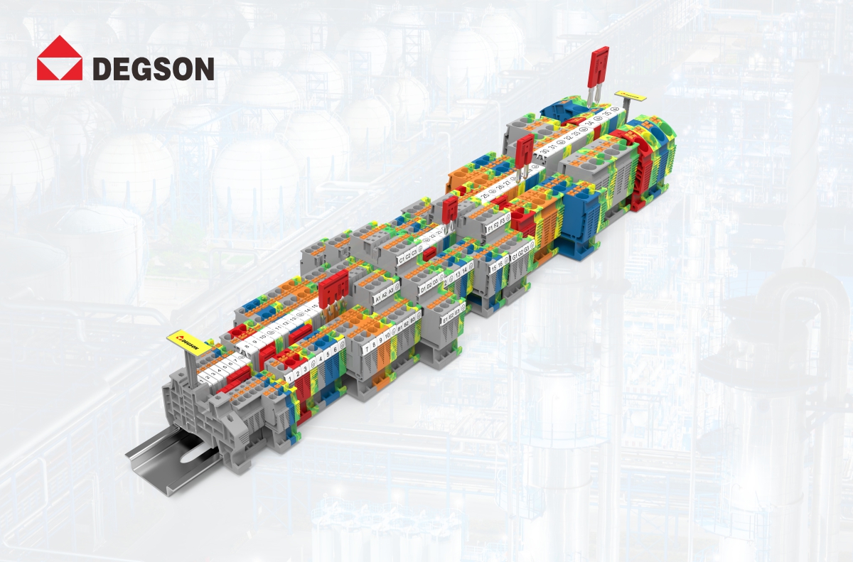
DEGSON's DIN-rail terminal blocks span five series by connection technology — push-in DS, screw DC and PC, spring-cage STB, stud BS — alongside fuse terminal blocks, PCB and pluggable connectors, and power distribution products. Any of these occupying a power circuit becomes a component entry under SB4.2, taking either a published rating or the Table SB4.1 default.
Request these four items before entering any terminal block into an SB4.4 calculation, from DEGSON or any supplier:
The UL file number for the specific series, plus its Follow-Up status on UL Product iQ — a cancelled or inactive file undermines the assembly calculation.
The listed component SCCR, or written confirmation that the Table SB4.1 default applies. A datasheet silent on SCCR means the default, not an unstated higher value.
Combination test data with specific current-limiting protection — fuse class, ampere rating, achieved SCCR — for any panel targeting 65 kA or 100 kA.
Peak let-through curves for any feeder-side arrangement relied on under SB4.3.3.
DEGSON's laboratory holds UL-CTDP, VDE-TDAP and CNAS approval (company profile) — the capability needed to generate combination test data of this kind, though the data itself still has to be requested per series.
One product-level clarification, because fuse terminal blocks are commonly misread on this point. The DSKK4-HE is a two-level fuse terminal block for G / 5 × 20 mm glass or ceramic fuses, rated IEC 400 V / 6.3 A and UL 300 V / 6.3 A, 0.2–6 mm² (24–10 AWG), push-in, PA housing UL 94 V-0, 6.2 mm wide. LED indication is a separate variant — DSKK4-HE-LD24 or -LD250 — not a feature of the base part.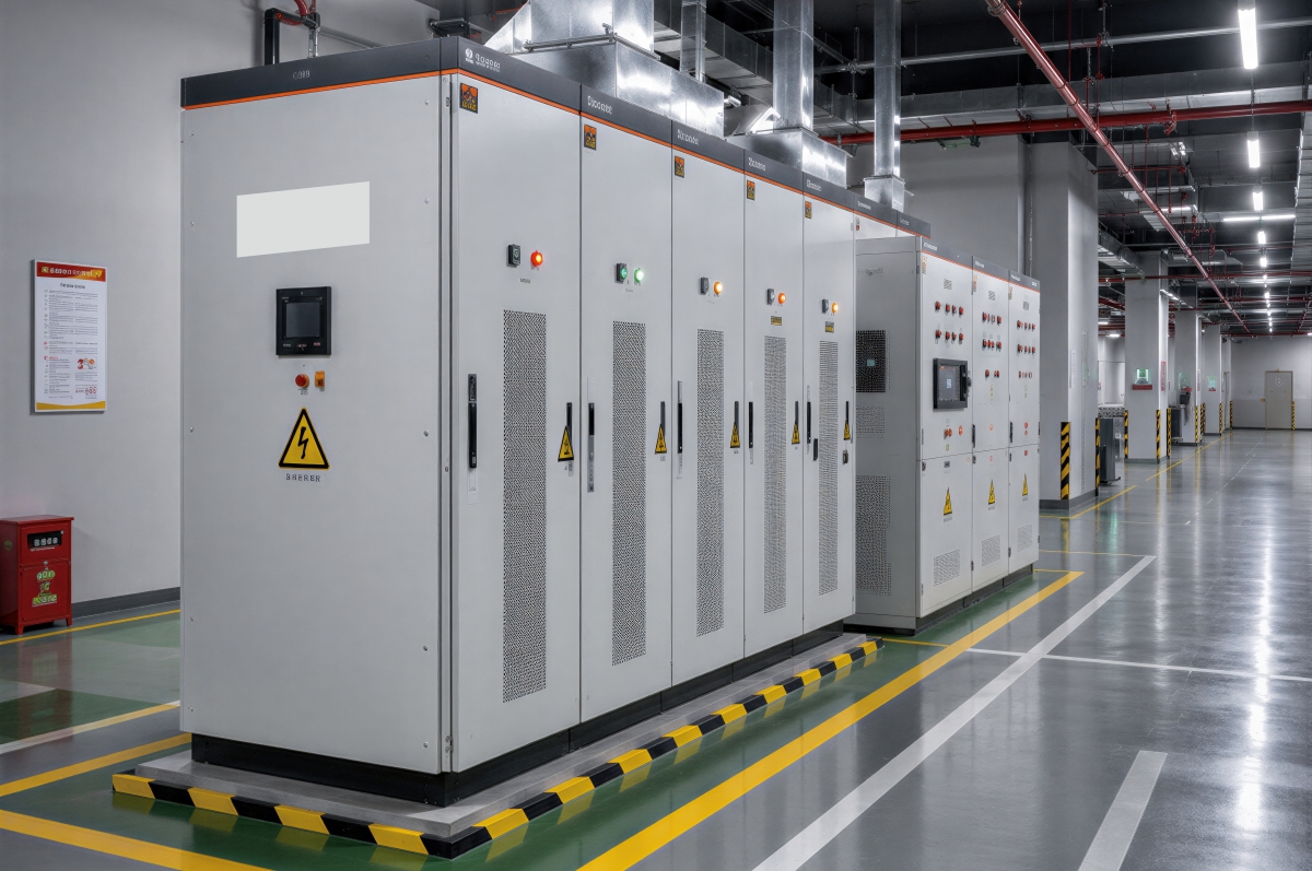
When a control panel nameplate states "SCCR 65 kA," that value is not a design target the engineer selected — it is the output of a calculation, capped by the weakest power-circuit component inside the enclosure, and mandatory marking under the NEC. Terminal blocks enter that calculation more often than any other component, and in most panels they enter at an assumed default rather than a tested value. This guide covers what SCCR means at component and panel level, how NEC Article 409 and UL 508A Supplement SB establish it, why current-limiting protection helps only from the feeder circuit, and what to request from a supplier before the calculation is run.
SCCR is a calculation result, and the weakest power-circuit component sets it
NEC Article 409 makes the marking mandatory, and UL 508A supplies the method
The component analysis method runs in three steps, and unmarked components take a default
Unmarked component
Assumed SCCR
Supplementary protector
0.2 kA
Receptacle, GFCI type
2 kA
Circuit breaker (including GFCI type)
5 kA
Industrial control equipment — switches, auxiliary devices (overload relay)
5 kA
Motor controller 0–50 hp (0–37.3 kW)
5 kA
Switch unit
5 kA
Multi-point interconnection power cable assembly
5 kA
Bus bars, current shunt, fuseholder, meter socket base
10 kA
Receptacle, other than GFCI
10 kA
Terminal block or power distribution block
10 kA
Motor controller 51–200 hp (38–149 kW)
10 kA
Motor controller 201–400 hp (150–298 kW)
18 kA
Motor controller 401–600 hp (299–447 kW)
30 kA
Current-limiting protection raises downstream ratings only from the feeder circuit
Condition
Resulting rating
Every downstream branch component's SCCR exceeds the feeder fuse's peak let-through current, and downstream branch-circuit protective device interrupting ratings (or controller-plus-device combination ratings) exceed the fuse's interrupting rating
The feeder fuse's interrupting rating
The first condition on let-through is met, but a downstream protective device has a lower interrupting rating
The smallest downstream protective device rating
Neither condition is met
The smallest SCCR among all downstream branch devices
How DEGSON terminal blocks enter the calculation, and what to request first
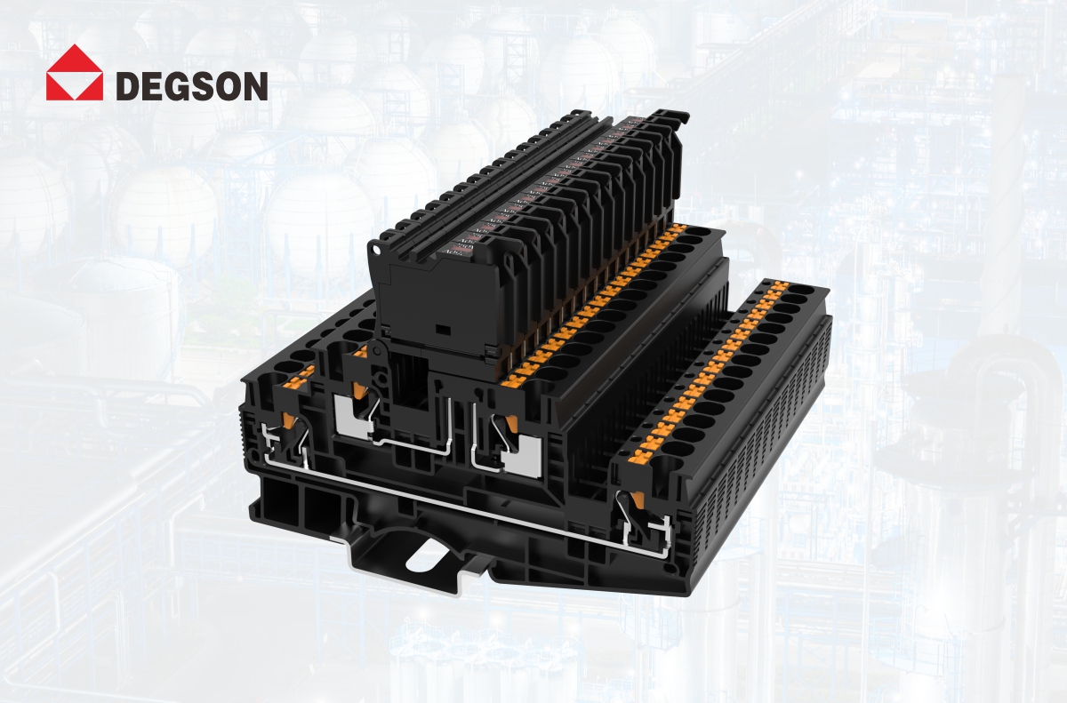
That specification places it in control-circuit protection and circuit isolation, not in SCCR modification. A 5 × 20 mm fuse is a supplementary type under UL 248-14; supplementary fuses and UL 1077 supplementary protectors cannot serve as branch-circuit protection, and a 6.3 A device is not a feeder component in a power circuit.
Applied to panel design, that leaves two rules. In power circuits, specify series with published SCCR data or with combination ratings documented against the protection actually installed — do not let a default-rated block cap the panel by omission. On high fault-current services, the only levers that work are a qualifying feeder-side current-limiting device, or components whose published ratings stand on their own.
One last distinction to keep out of the calculation: the current and voltage ratings on a rail-mount datasheet — DS2.5 at IEC 800 V / 24 A and UL 600 V / 20 A, for instance — are load ratings under IEC 60947-7-1 and UL 1059. They are not SCCR values and cannot substitute for one.
FAQ
Does a UL 94 V-0 terminal block have a high SCCR? No — the two are unrelated properties. UL 94 V-0 describes how the housing material behaves in a flammability test. SCCR is an electrical withstand rating established per UL 508A Supplement SB, either from a tested and marked component value or from the Table SB4.1 default. A V-0 housing tells you nothing about whether the block enters your calculation at 10 kA or at a tested higher value, and no combination of material ratings, temperature range or current rating substitutes for a published SCCR.
Can I install a current-limiting fuse ahead of a terminal block to raise the panel SCCR? Only if that fuse is in the feeder circuit and is one of the classes SB4.3.3 recognises — CC, G, J, L, RK1, RK5 or T. A current-limiting device in the branch circuit does not raise the SCCR of the terminal blocks in that branch; they remain the weakest component and continue to set the rating. Even with a qualifying feeder fuse, the resulting value depends on the comparison in SB4.3.3: the fuse's peak let-through current against the downstream components' SCCR, and the fuse's interrupting rating against the downstream protective devices'. The fuse's own 200 kA interrupting rating is not a number the components behind it inherit.
References
-
NFPA 70, National Electrical Code — Articles 100, 110.9, 110.10, 409.22, 409.110(4). NFPA
-
UL 508A, Standard for Industrial Control Panels, Supplement SB — SB4.1 through SB4.4.
-
UL Solutions, Determining SCCR for Machinery — terminal block 10 kA default; power supply treatment. ul.com
-
Rockwell Automation, Short-circuit Current Ratings and Your Industrial Control Panel (SCCR-AT002) — the SB4.2 / SB4.3 / SB4.4 steps and SB4.3.3 fuse classes. literature.rockwellautomation.com
-
UL 248 series and UL 1077 — the basis for distinguishing branch-rated from supplementary protection.
-
UL Product iQ — verifying component UL file numbers and Follow-Up status. productiq.ulprospector.com
Take the next step
Before your next UL 508A submittal, pull the four documentation items above for every terminal block series sitting in a power circuit. DEGSON publishes datasheets, 2D drawings and CAD models per SKU at degson.com; for series-level UL file numbers and combination SCCR test data, request them from DEGSON application engineering — state your target panel SCCR, nominal voltage and the specified overcurrent protection in the request, since the answer depends on all three.


