How to Choose a Wiring Method for High-Power PCB Terminal Blocks: Screw, Spring Cage, and Lever-Actuated Push-In Compared
For a board-mounted power connection in the 6–16 mm² range, three things decide the wiring method: whether the assembly line can absorb the tool time and torque control that screws require, whether the terminal must be measured without disconnecting the conductor, and which rating system — IEC or UL — governs your target market. Get those three answered and the choice narrows to one or two candidates. This guide covers PCB-mounted terminal blocks for inverters, servo drives and power supplies, evaluated under IEC 60947 and UL 1059. It does not cover DIN-rail terminals (IEC 60947-7-1) or rail-vehicle applications, where EN 45545 fire-and-smoke requirements govern material selection independently of the clamping method.
Four variables decide the wiring method before any part number
The clamping principle is not a preference — each of these four variables can eliminate a whole category.
Conductor cross-section and operating force. Screw clamping is indifferent to conductor stiffness but scales badly with size: a 16 mm² conductor needs both a defined torque and enough clearance for a screwdriver to reach it perpendicular to the board. Spring clamping removes the torque spec entirely, but a plain push-in spring stiff enough to hold 16 mm² also requires real insertion force from the operator. A lever moves that force into a mechanical advantage, which is why lever actuation appears mostly at the top of the cross-section range rather than the bottom.
Tool dependency and line time. Screw terminals require a torque-controlled driver and a torque record if the assembly is audited. Push-in springs need no tool for solid or ferruled conductors, but fine-stranded conductors without ferrules still need a release tool. Levers remove the tool from both directions — connect and release — which matters most for field service, where the technician may not carry the right driver.
Measurement without disconnection. If the terminal is a test point during commissioning, a dedicated test hole is a hard requirement, not a convenience. Without one, verifying continuity or voltage means loosening a live power conductor.
Entry angle and cabinet space. A lever needs swept volume to open. On a densely populated board, a 0° (horizontal) entry with a lever can demand more clearance in front of the connector than a 90° screw terminal does above it. Confirm the open-lever envelope against the CAD model, not the closed-state footprint.
Three clamping principles compared on what can be verified
The table below compares only properties that appear on a datasheet or a test report. Figures such as installation time savings are excluded deliberately — see the note that follows.
| Property | Screw clamping | Spring Cage | Lever-actuated push-in |
|---|---|---|---|
| Tool to connect | Torque-controlled driver | Driver to open the spring | None |
| Tool to release | Driver | Driver | None |
| Torque spec to record | Yes | No | No |
| Fine-stranded without ferrule | Accepted | Accepted | Ferrule or solid preferred |
| Hold-open during wiring | Not applicable | No — spring closes | Yes, lever stays open |
| Integrated test hole | Rarely | Sometimes | Yes, in the lever on the DLS series |
| Vibration behaviour | Depends on retained torque | Spring-maintained | Spring-maintained |
| Typical PCB cross-section ceiling | 16 mm² and above | ~6 mm² | 16 mm² |
| Governing standard (PCB, fixed) | IEC 60947 / UL 1059 | IEC 60947 / UL 1059 | IEC 60947 / UL 1059 |
| Governing standard (pluggable) | IEC 61984 / UL 1059 | IEC 61984 / UL 1059 | IEC 61984 / UL 1059 |
Two boundaries are worth stating plainly. Spring clamping does not remove the need for correct strip length — an over-stripped conductor in a push-in terminal leaves bare copper outside the clamp, and an under-stripped one never reaches the contact. DEGSON's lever-actuated parts specify this explicitly: 10–11 mm for the 5.0 mm pitch DG2204, 12 mm for the 7.5 mm DG2206, and 18 mm for the 16 mm² DG2216. And a hold-open lever is only an advantage where multiple conductors are landed in sequence; for a two-pole connection it saves nothing.
On wiring-time claims: published figures for tool-free versus screw connection range from roughly 60% to over 80% depending on what is being compared and how it is timed. None of the sources state conductor size, pole count, baseline part number, sample size or timing method, so no single percentage should be treated as a specification.
Read the rating system before comparing any two numbers
A single part number legitimately carries two different voltage ratings, and comparing across the two is the most common selection error in this category.
IEC 60947 rates a terminal against a combination of overvoltage category and pollution degree. The same DG2204 block is rated 320 V at III/3, 400 V at III/2, and 630 V at II/2 — one product, three numbers, all correct. The III/2 column is the one normally quoted in a catalogue, so a "400 V" part is a 320 V part in a dirtier environment.
UL 1059 instead assigns a use group. For the DG2206, groups B and C are rated 600 V / 41 A while group D is rated 600 V / 5 A. The current collapses by a factor of eight between use groups on the same product — which is why quoting "41 A UL" without the group is meaningless.
Put side by side, the two systems produce numbers that look contradictory but are not:
| Series | Pitch | IEC III/2 | UL group B/C | Cross-section | AWG | Strip length |
|---|---|---|---|---|---|---|
| DG2204 | 5.0 mm | 400 V / 32 A | 300 V / 20 A | 0.2–4 mm² | 24–12 | 10–11 mm |
| DG2206 | 7.5 mm | 1000 V / 41 A | 600 V / 41 A | 0.2–6 mm² | 24–8 | 12 mm |
| DG2216 | 10.0 / 15.0 mm | up to 1000 V / 76 A | up to 600 V / 66 A | 0.2–16 mm² | 18–4 | 18 mm |
| 5EDGKDL (plug) | 7.62 mm | 1000 V / 41 A | 600 V / 42 A | 0.2–6 mm² | 20–8 | 12 mm |
| 5EDGRL / 5EDGVL (header) | 7.62 mm | 630 V / 41 A | 300 V / 41–42 A | — | — | — |
The last row carries a consequence that is easy to miss: a mated pluggable pair is limited by the lower-rated half. The 5EDGKDL-7.62 plug is rated 1000 V under IEC, but its matching 5EDGRL and 5EDGVL headers are rated 630 V, so the assembly is a 630 V assembly. Rating the connection from the plug datasheet alone overstates it by one full category.
Pin arrangement, not pitch, sets the IEC voltage on a 16 mm² block
Two DG2216 order codes share the same series, the same 15.0 mm pitch, the same 16 mm² cross-section, the same PA66 UL94 V-0 housing and the same −40 to +105 °C range — and are rated a full category apart:
| Order code | Pin arrangement | IEC rated voltage | IEC current | UL B/C | Surge |
|---|---|---|---|---|---|
| 10060007957 | Double-row in a straight line | 600 V | 76 A | 300 V / 66 A | 6 kV |
| 10060007955 (–DB) | Double-row, staggered | 1000 V | 76 A | 600 V / 66 A | 8 kV |
The difference is geometric, not electrical: staggering the two rows lengthens the clearance and creepage path between adjacent potentials, and both the IEC voltage and the surge withstand follow. The current rating is unaffected, because current is set by the contact and conductor, not by the spacing between poles.
The practical consequence is that "DG2216" alone is not a specification. A design that needs 1000 V under IEC III/2 must call out the staggered variant by order code; substituting the in-line variant during a shortage silently drops the assembly to 600 V. Verify the pin arrangement line on the specific order code's datasheet — not the series page — before release to production.
Where the DLS lever-actuated series fits, and where it does not
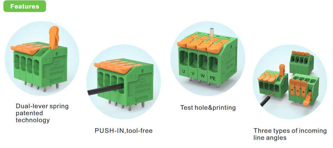
DEGSON's DLS (Dual-Lever Spring) construction combines a push-in spring with a lever on each pole, covered by Chinese utility model application ZL201921625513.6 (cited on the DG2216R and DG2206R datasheets). Against the four variables above, it fits these conditions:
-
16 mm² at 66 A UL / 76 A IEC without a torque spec — the DG2216 is the only member of the family reaching 16 mm²; the DG2204 stops at 4 mm² and the DG2206 at 6 mm². A blanket "handles 16 mm²" statement across the series is wrong.
-
Terminals used as commissioning test points — the test hole is in the lever itself, so continuity and voltage can be measured without releasing the conductor.
-
Sequential multi-conductor landing — levers can be left open, so all poles are prepared before any conductor is inserted.
-
Field service without a tool kit — both connect and release are tool-free.
-
Constrained entry geometry — DG2204 and DG2206 offer 0° / 45° / 90° entry; DG2216 offers 0° / 90° only.
It does not fit these cases. Where the connection must be separable for module replacement, the fixed PCB variants are the wrong choice — their datasheets state "Pluggable or not: no", and a separable connection requires the 5EDGKDL plug with a 5EDGRL or 5EDGVL header, at 630 V IEC for the mated pair. Where fine-stranded conductors are used without ferrules, confirm the conductor preparation the datasheet accepts. Where the cabinet cannot give the lever swept volume, a 90° screw terminal may still be the smaller installed envelope. And for rolling stock, material compliance is governed by EN 45545 rather than by UL 94 alone, so the PA66 V-0 rating on these parts does not by itself qualify them.
Vibration behaviour deserves one caution. DEGSON's datasheets describe "lent anti-vibration performance" for the push-in spring construction, but state no test level. A spring-clamped connection does not need retained torque, which is the usual failure mode of screw terminals under vibration — but "no torque to lose" is a mechanism, not a qualification. Ask for the IEC 60068-2-6 frequency band, acceleration and duration before relying on it.

FAQ
Can I use the IEC 1000 V rating for a product sold in North America?
No. The UL rating is a separate evaluation under UL 1059 with its own use groups, and it is the figure a North American inspection will reference. On the DG2206 the two systems differ by a full step — 1000 V under IEC III/2 versus 600 V under UL groups B and C — and on the staggered DG2216 the gap is the same. Specify against the rating system that governs the destination market, and where a product ships to both, design to the lower of the two.
Does a tool-free terminal still need a defined strip length?
Yes, and it is the most common assembly defect in push-in connections. The clamp engages the conductor over a defined window: 10–11 mm on the DG2204, 12 mm on the DG2206 and 5EDGKDL, 18 mm on the DG2216. Over-stripping leaves bare conductor outside the insulator; under-stripping stops the conductor short of the contact and produces an intermittent joint that passes a continuity check and fails under load. A transparent-housing or marked strip gauge helps, but the dimension still belongs in the work instruction.
References
-
IEC 60947 series, Low-voltage switchgear and controlgear — overvoltage category and pollution degree combinations.
-
UL 1059, Standard for Terminal Blocks — use groups B, C and D.
-
IEC 61984, Connectors — Safety requirements and tests — applicable to pluggable variants rather than fixed PCB blocks.
-
DEGSON DG2216R-15.0 and DG2216R-15.0-DB official datasheets, order codes 10060007957 and 10060007955 — pin arrangement and IEC/UL ratings.
-
DEGSON 5EDGKDL-7.62 product page — mated-pair rating limits with 5EDGRL / 5EDGVL headers.
Take the next step
Confirm your selection against the order-code datasheet rather than the series page: the pin arrangement, use group and strip length all live there. DEGSON publishes 2D PDF drawings and CAD models (STP / DXF) on each SKU page at degson.com — the DG2204, DG2206, DG2216 or 5EDGKDL model that matches your entry angle and check the open-lever envelope against your board layout before committing. For the IEC 60068-2-6 vibration report, UL file number, or a sample for conductor-preparation trials, request them from DEGSON technical support with your target market and pollution degree stated.


