Six Hidden Safety Risks in Type 1 (SAE J1772) Connectors
The Type 1 connector (SAE J1772, also known as the J-Plug) is the de facto standard for single-phase AC charging across North America and Japan. Its five-pin design covers everything from 120V Level 1 to 240V/80A Level 2 (up to 19.2 kW). L / N / PE carry the power, the CP (Control Pilot, 1 kHz PWM) handles vehicle-to-charger handshakes, and the PP (Proximity Pilot) reports cable current rating via resistor values (2.7 kΩ ≈ 16 A, 1.3 kΩ ≈ 32 A) while interlocking with the mechanical latch. The standard is mature — which is exactly why it is so often overlooked during sourcing. The six hazards below can each escalate from a minor annoyance into a fire-level incident.
Pin oxidation, carbon buildup, poor plating, or loose terminals all drive up contact resistance. Using P = I²R as a rough estimate, a single 0.05 Ω contact point continuously generates around 51 W of heat at 32 A. Even more dangerous: many low-cost units omit the built-in NTC temperature sensor inside the plug entirely, leaving the control system blind while the pins glow red. In residential charging fires, the ignition point is often neither the station nor the car — it is the plug-to-pin contact interface.
Field service data indicates that roughly 73% of J1772-related faults involve PP signal drift, and the root cause is almost always a failed boot seal at the cable-to-cable junction. Rainwater and de-icing salt spray seep in and corrode the PP solder joint, shifting the resistance value. The vehicle then misjudges the cable's current capacity, actively throttling charge power or refusing to charge altogether. In severe cases, charging starts and cuts out within seconds—users blame the car or the station, when in reality the plug seal has simply degraded.
That faint black, fingerprint-like deposit on the contact surface is not dirt—it is a carbide film formed by thermal decomposition of the metal under repeated micro-arcing. It starts on the thinnest signal pins (CP/PP), which carry the least contact pressure, and once established, it enters a vicious cycle: more carbon → more heat → more carbon. Many drivers complain that "charging keeps getting slower" and assume battery degradation, but carbon buildup on the plug pins is often the real culprit.
The Type 1 safety sequence is "disconnect PP first, cut power, then unplug." If the plastic latch wears out or the spring fatigues, two dangerous scenarios arise: first, the plug can pop out mid-charge, producing an arc that burns the pin surface at 32 A / 240 V; second, the plug may click into place but sit at insufficient insertion depth, causing local overheating.
When mated, outdoor stations should meet IP55 or even IP67; when unmated, both the vehicle inlet and the plug should have protective covers. Cheap products use ordinary TPE for the seal—one winter of low-temperature hardening and UV brittleness is enough to crack it. Water ingress into the charging port after heavy rain, or repeated GFCI trips, is almost always a cracked seal.
Tesla-to-J1772 adapters and cheap extension cords are the worst offenders: brass nickel-plated pins instead of silver-plated copper alloy, no onboard temperature sensing, undersized conductors (marked 12 AWG, actually 14 AWG), and housings that fail UL94 V0 flame rating. The safety boundary of the entire charging chain is defined by its weakest component.
Stacked against the checklist above, DEGSON's Type 1 (SAE J1772) line hits nearly every pain point head-on:
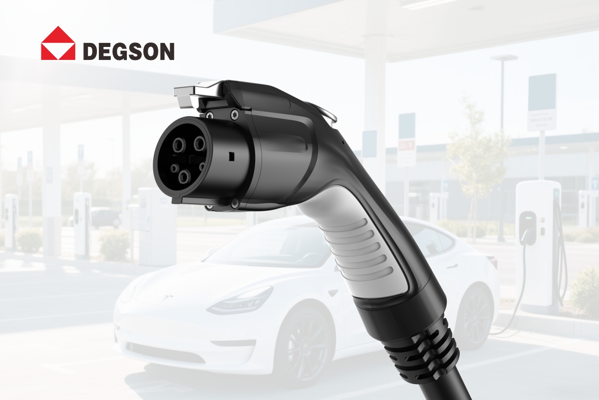
- Full silver-plated contacts — both power and signal pins are silver-plated, delivering significantly lower contact resistance than nickel-plated alternatives, and suppressing pin burning and carbon buildup at the source (addresses hazards #1, #3).
- IATF 16949:2016 automotive-grade system — from material sourcing to traceability, the entire process runs to automotive rather than consumer-electronics standards, built for 24/7 outdoor stations and fleet customers.
- In-cable thermal control + IP67 rating — built-in NTC real-time temperature monitoring with over-temperature protection; IP67 cable body plus multi-layer root sealing effectively mitigates PP signal drift and water short-circuits (addresses hazards #2, #5).
- High-strength metal latch + UL94 V0 housing — secure locking without arcing; the housing self-extinguishes and will not fuel a fire under extreme conditions (addresses hazards #4, #6).
- Unified design platform — vehicle plugs and station-side sockets are engineered on the same platform, so portable cables, wallboxes, and DC fast-charger AC sides can all be specified from one source, reducing interface compatibility risk.
Founded in 1990, with UL-CTDP, VDE-TDAP, and CNAS accredited laboratories, 400+ patents, and six global production bases. The EV charging connector portfolio covers Type 1 / Type 2 / GB/T / CCS / NACS, with on-board high-voltage connectors compliant with USCAR-2 / LV215.


