PV Inverter and Energy Storage Connector Selection (2026): A Position-by-Position Guide from String to Battery Rack
Select PV and energy-storage connectors by connection position, not by product family. Each position — PV string DC, inverter AC output, inverter signal, battery module and rack, rack-to-PCS link, BMS/EMS signal — has its own voltage class, current, environment and qualification standard: IEC 62852 or UL 6703 for PV DC connectors, UL 4128 for battery intercell and intertier connectors. Two rules override every datasheet figure: never mate PV connectors of different manufacturers, and never use a connector to break load current unless it is rated to do so.
This guide applies to residential, commercial and utility PV-plus-storage systems up to 1500 V DC on the DC side and low-voltage AC on the grid side. It does not cover systems above 1500 V DC (outside the scope of IEC 62852), medium-voltage grid connection, marine or offshore installations, or EV charging interfaces, which follow their own standards.
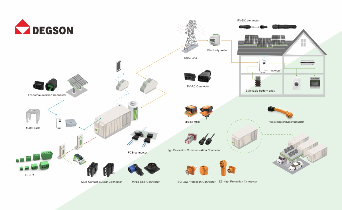
Map the connector positions before choosing a productA PV-plus-storage system has at least six connector positions, and they fail for different reasons. A PV string connector fails from water ingress, UV and mismatched mating; a battery rack connector fails from overheating at hundreds of amps or from being opened under load; a signal connector fails from a swapped harness. Listing the positions first stops one product family's datasheet from being applied everywhere.
| Position | Typical duty | Environment | Qualification basis | First check |
|---|---|---|---|---|
| PV string → combiner / inverter DC input | Up to 1500 V DC, tens of amps per string | Outdoor, UV, rain, −40 °C to +85 °C | IEC 62852 / UL 6703 | Same-brand mating; rating ≥ 1.56 × Isc (NEC) |
| Inverter AC output | Low-voltage three-phase AC, tens of amps | Indoor or semi-outdoor | Connector and inverter product standards | Continuous current at internal temperature; locking |
| Inverter communication | RS-485, CAN, Ethernet; low voltage, ≤ a few amps | Enclosure wall, often outdoor | Manufacturer specification, IP rating | Pin coding; sealing at the wall |
| Battery module / rack (intercell, intertier) | Up to 1500 V DC, 50–600 A | Enclosed cabinet, often liquid-cooled | UL 4128 | Not for disconnection under load; touch protection |
| Rack / cluster → PCS | Up to 1500 V DC, hundreds of amps | Cabinet, busbar or cable | UL 4128; system listing to UL 9540 | Service disconnect and interlock strategy |
| BMS / EMS signal; residential and portable storage | Low-voltage signal; 20–50 A for small storage | Crowded cabinet; handled by non-specialists | Manufacturer specification | Secondary lock, polarity coding, finger-safe contacts |
PV string DC connectors: rating, sealing and the same-manufacturer rule
IEC 62852 covers connectors for the DC circuits of PV systems in class II construction, with rated voltages up to 1500 V DC and rated currents up to 125 A per contact. It applies to connectors without breaking capacity: they may be engaged and disengaged while voltage is present, but not while load current flows. Open the inverter's DC switch or the string disconnect first.
Size current from the module, not from the connector's headline. In NEC jurisdictions the maximum PV source-circuit current is 125% of the module short-circuit current (Isc), and conductors and components carry a further 125% for continuous duty — 1.56 × Isc in total. PV connector ratings are usually stated per conductor size, so check the rating for the cross-section actually used and the derating at the rooftop or tracker ambient.
Mate only identical type and brand. Many PV connectors look alike, but IEC 62852 and UL 6703 qualify a connector only with its own counterpart. Stäubli's guidance on cross-mating and the NEC 2020 wording of 690.33(C) put the rule plainly: mating connectors must be of identical type and brand, or listed and identified for intermatability. In practice, match field-assembled string connectors to the connector already fitted to the module, and record the brand and type in the as-built documentation.
Sealing is a mated-and-crimped property. An IP67 or IP68 rating applies to a correctly crimped, fully mated pair with the specified cable diameter. Unmated connectors need sealing caps; the crimp must be made with the manufacturer's tool and die; and the cable must fall inside the gland's diameter range. A connector rated above 1500 V DC is outside IEC 62852's scope, so ask which standard and certificate its rating is based on.
Inverter AC output and signal connectors: current margin, locking and codingAC output connectors carry continuous current inside a warm enclosure. Select from the connector's derating curve at the internal air temperature, not from its rated current at room temperature. Where one housing carries both grid-side and load-side (backup) circuits, the pins may have different ratings; check each circuit separately.
Mechanical retention matters as much as rating. A positive latch with a secondary lock, and a release that needs a tool, stops a connector from being pulled apart during installation or service. Touch-protected sockets matter on the side that stays live.
Communication connectors — RS-485, CAN, Ethernet — fail in the field from swapped harnesses and from moisture at the enclosure wall far more often than from electrical overload. Specify coded variants for connectors of the same pin count at the same location, so two harnesses cannot be exchanged. Check the IP rating of the mated pair at the panel cut-out, and terminate cable shields over 360° at the connector or gland.
Battery-side connectors: high current, touch safety and UL 4128Battery module and rack connectors are covered by UL 4128, the outline for intercell and intertier connectors in electrochemical battery systems. These are cable connectors with mating inlets, for copper conductors rated 90 °C or higher. Recent editions raised the voltage limit to 2000 V DC. They are not intended for connection or disconnection under load. That single line shapes the whole service design:
-
Isolate before unplugging. Open the rack contactor or breaker, or pull the manual service disconnect (MSD), before any battery connector is separated. The connector is not the switch.
-
Use an interlock where the design allows. A high-voltage interlock loop (HVIL) signals the BMS when a connector or cover is opened, so the contactors open before a contact separates under current.
-
Touch protection and polarity coding. Finger-safe sockets, colour coding and mechanical coding for positive and negative prevent both shock during service and reversed connections at commissioning.
-
Current and temperature. At 50–600 A, contact resistance and conductor cross-section decide temperature rise. Ratings are tied to a specific cross-section, and liquid-cooled cabinets can still have hot spots at the rack connectors.
-
Mating cycles are limited. Battery connectors are designed for installation and occasional service, not frequent plugging. A datasheet can list as few as 100 mating cycles, so plan maintenance procedures around the figure for the exact part.
Residential and portable storage adds a different risk: the person plugging the connector may not be an electrician. At 20–50 A, current is rarely the limit; finger-safe contacts, polarity coding, clear marking and a latch that confirms engagement matter more.
Five checks before approving a connectorBefore a connector goes onto a bill of materials, confirm five things for the exact part number:
-
Certificate for the right position. A PV DC connector should be certified to IEC 62852 or UL 6703; a battery rack connector to UL 4128. Check the certificate in the issuing body's database, such as UL Product iQ or TÜV Rheinland's Certipedia, and confirm that it names the part number.
-
Rating at your conductor size and ambient. Read the rated current for the cross-section used and the derating curve for the installed temperature.
-
Mated IP rating and the unmated condition. Confirm the IP rating of the mated pair, the cable diameter range and the protection for unmated connectors.
-
Mating partner and tooling. Confirm same-brand, same-type mating, and the crimp tool and die the manufacturer requires.
-
Load-break behaviour and service procedure. Confirm whether the connector may be separated under voltage or load, and which switch, MSD or interlock isolates it first.
DEGSON's range covers each position in the table above. Its official product pages give the following ratings for representative part numbers.
-
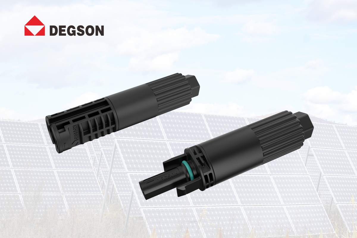
PV string DC. The PV-DC connector (quick-install) is rated 1500 V DC, 30 A with 4.0 mm² (12 AWG) and 35 A with 6.0 mm² (10 AWG) cable, IP68, −40 °C to +85 °C, UL94 V0. It is terminated by stripping and plugging, without a crimp tool. The fused PV-DC connector is rated 1500 V DC and 35 A (30 A in its UL parameters), IP68. DEGSON's brochure also shows a 2000 V DC / 40 A / IP68 variant; because 2000 V is outside IEC 62852, confirm its certification basis before use.
-
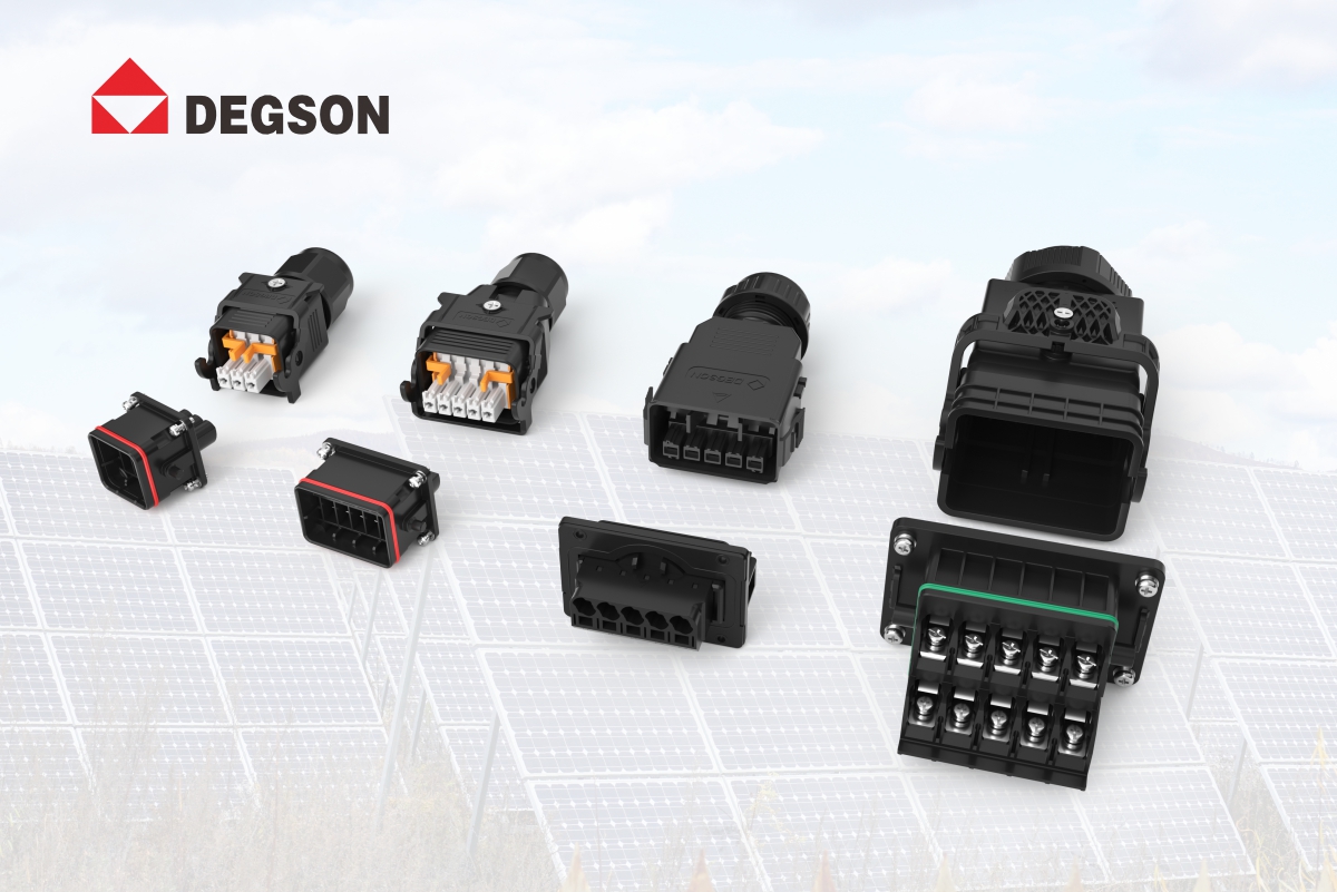
Inverter AC and communication. According to DEGSON's brochure, the 5-pin AC power connector is rated 600 V / 65 A. The 10-pin version is rated 600 V, 65 A on the grid circuit and 30 A on the load circuit — an example of per-circuit ratings in one housing. Both have quick locking and secondary tool unlocking. The 12- and 18-pin communication connectors are rated 250 V / 1.5 A; the ET high-protection communication connectors are rated 300 V / 5 A with 8–24 pins, a secondary lock, and two coded variants for each pin count.
-
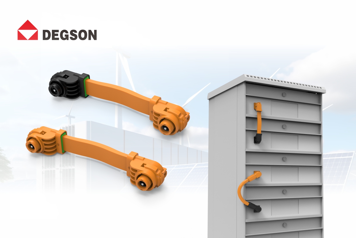
Battery module, rack and PCS link. ESS-200A-50-B-OR-90 is rated 1500 V / 200 A for 50 mm² busbar connection, with contact resistance ≤ 0.5 mΩ, IP67, −40 °C to +125 °C and UL94 V-0. It lists 100 mating cycles and is built to UL 4128, with finger-safe sockets and colour and mechanical coding. ESP-400A-250-BK-00 is rated 1500 V / 400 A for a 127 mm² (250 kcmil) crimped conductor, ≤ 0.5 mΩ, IP67, with TÜV and UL listed on its page. According to the brochure, MSD/FMSD service disconnects come in 200 A and 350 A versions with an optional fuse and a high-voltage interlock.
-
-
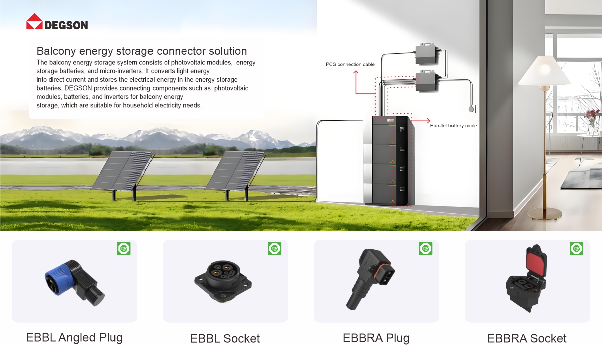
Residential and portable storage.According to the brochure, the EBBL series (20–50 A) is aimed at portable storage and small stations, and the EBBRA series (50 A) at parallel connections in balcony storage.
Two boundaries apply. The AC, communication, MSD, EBBL and EBBRA figures above come from DEGSON's brochure, not from a published datasheet. The 100-cycle rating of ESS-200A-50-B-OR-90 also shows that battery connectors must not double as service switches. Confirm every value against the datasheet and certificate of the exact order number before approval.
Can I mate a PV connector from one brand with a "compatible" connector from another brand? Not unless the pair is listed and identified for intermatability. IEC 62852 and UL 6703 qualify a connector only with its own counterpart, and NEC 2020 690.33(C) requires mating connectors of identical type and brand otherwise. Look-alike connectors can differ in contact geometry, plating and seal dimensions, and the combination has never been tested.Can I unplug a battery rack connector to isolate the rack?No. Connectors evaluated under UL 4128 are not intended for connection or disconnection under load. Open the rack contactor, breaker or manual service disconnect first. Where the design includes a high-voltage interlock loop, let it confirm that the circuit is de-energized before any connector is separated.
-
1. IEC 62852:2014 — Connectors for DC-application in photovoltaic systems: safety requirements and tests. https://webstore.iec.ch/en/publication/7463
-
2. UL 4128 — Outline of Investigation for Intercell and Intertier Connectors for Use in Electrochemical Battery System Applications. https://standardscatalog.ul.com/ProductDetail.aspx?productId=UL4128
-
3. Mayfield Renewables — PV connector mating and intermatability in NEC 2020 (690.33). https://www.mayfield.energy/technical-articles/pv-connector-mating-and-intermatability-in-nec-2020/
-
4. Stäubli — Avoid cross-mating: only link same-manufacturer PV connectors. https://www.staubli.com/us/en/electrical-connectors/industries/renewable-energy/cross-connection.html
-
5. Penn State AE 868 — Conductor and wire sizing for PV systems (NEC 690.8). https://courses.ems.psu.edu/ae868/node/966
-
6. DEGSON — PV-DC connector (quick-install). https://www.degson.com/content/details_552_5184202.html?lang=en
-
7. DEGSON — PV-DC connector (with fuse). https://www.degson.com/content/details_552_5184201.html?lang=en
-
8. DEGSON — ESS-200A-50-B-OR-90 energy storage connector. https://www.degson.com/content/details_552_4438138.html?lang=en
-
9. DEGSON — ESP-400A-250-BK-00 energy storage connector. https://www.degson.com/content/details_552_4930182.html?lang=en
Start with the position table: list every connector position in your PV-plus-storage design, the standard that applies to it, and the switch or interlock that isolates it. Then run the five checks against the exact part numbers. To evaluate DEGSON parts, open the PV-DC and energy-storage connector pages on degson.com, the datasheet for the order number, and request the TÜV or UL certificate and samples for the positions you are specifying.


