How Do Battery-Swapping Connectors Survive Dozens of Daily Matings? Deconstructing High-Frequency Cycling, Float Alignment and Power-on Communication
A battery-swapping rider changes batteries two to three times a day. Over three years, that is more than 2000 mating cycles on a single connector. Yet swapping stations report that within six to twelve months, connectors begin showing terminal wear, intermittent BMS data reading, and difficulty aligning during insertion. The root cause is almost never the connector being poorly made — it is that a standard charging connector, designed for weekly use, was deployed into a daily high-frequency swapping environment without the mechanical life, alignment tolerance or communication architecture that swapping requires.
The single most important point: a swapping connector is not a charging connector used more often. It is a different product category with four distinct requirements — mechanical life measured in thousands of cycles, mechanical alignment tolerance for robotic or rider insertion, positive/negative insertion to eliminate orientation errors, and integrated signal channels so the swapping cabinet reads battery data the instant power connects. Using a standard connector in this role is a guaranteed field failure.
This guide covers battery-swapping connectors used on electric bicycles, e-motorcycles and electric three-wheelers in rider-swapping and cabinet-swapping scenarios.
Field scenario:
A swapping station deploys standard e-bike charging connectors because they are cheaper and readily available. Within six months, terminal contact resistance rises, BMS data drops out intermittently, and riders complain that the battery is hard to insert. The connector has not broken — it has simply exceeded its design cycle count.
Mechanism:
A standard charging connector is typically designed for 500-1000 mating cycles, reflecting weekly home charging over several years. At two swaps per day, that threshold is reached in under a year. After the design cycle count, terminal plating wears through, contact resistance increases, and the spring contact force degrades. The connector still works — but intermittently, and with rising temperature at the contact point.
How DEGSON addresses it:
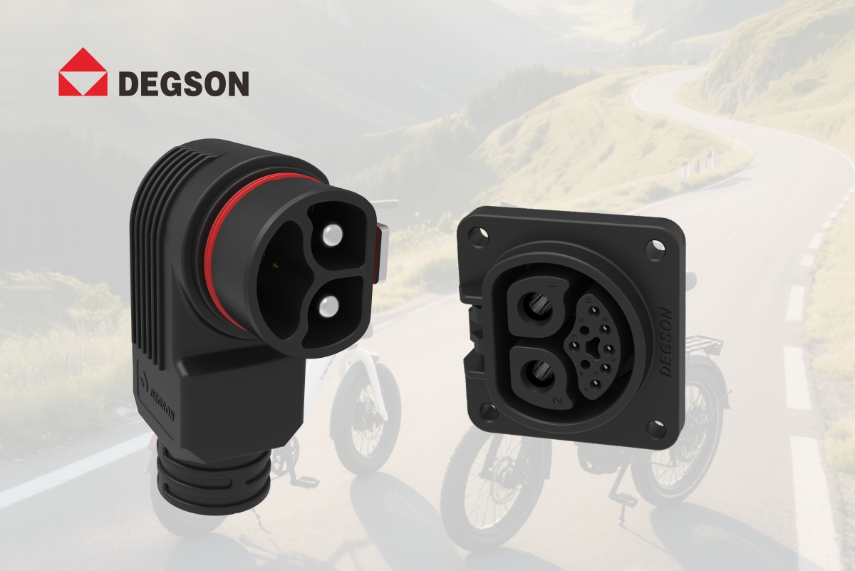
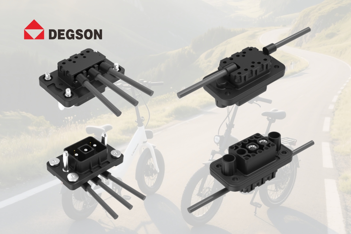
The DEGSON EBBH power connector series specifies a mechanical life of >=3000 cycles, with stable contact resistance and no IP rating degradation after cycling. At two swaps per day, >=3000 cycles covers over four years of operation. The EBBH auto-locks on full mating with extraction force >50N, preventing disconnection under swapping cabinet vibration. For dedicated swapping applications, the DEGSON EBBF swapping connector series is purpose-built for high-frequency cycling with guide-pin alignment, float compensation and positive/negative insertion.
The problem:
In a swapping cabinet, the battery slot and the battery itself never align with zero tolerance. Sheet metal tolerances, cabinet frame flex, battery pack dimensional variation, and rider insertion angle all contribute to a gap of several millimeters between the ideal alignment position and the actual position. A connector with zero alignment tolerance will bind, scratch terminals, or fail to mate fully.
Two design features solve this:
First, guide pins — tapered lead-in pins that mechanically funnel the connector into alignment as the battery slides in, even if the initial position is off by several millimeters. Second, float compensation — the connector housing is mounted with a degree of lateral and angular float, allowing it to self-center during mating rather than forcing the battery into an exact position.
How DEGSON addresses it:
The DEGSON EBBF swapping connector features guide-pin alignment and float compensation. The guide pins ensure the connector aligns during insertion even when the battery position varies. The float amount compensates for assembly gaps between the vehicle body and battery, facilitating fast alignment by swapping cabinet robots or riders. This eliminates the bind-and-scratch failure mode that damages terminals in non-floating connectors.
The problem:
A keyed connector that only mates in one orientation works fine when the user has time to look. But in a swapping station, a rider under time pressure may attempt to insert the battery in the wrong orientation. If the connector is single-orientation only, this causes forceful mis-mating, terminal damage, and rider frustration. In robotic swapping, the cabinet must also handle batteries that may be loaded in either orientation.
The solution:
Positive/negative insertion — the connector is designed to mate correctly regardless of which orientation the battery is inserted. The pin arrangement and housing geometry are symmetric, so either orientation produces a valid electrical connection. This eliminates orientation errors entirely and reduces insertion time.
How DEGSON addresses it:
The DEGSON EBBF swapping connector supports positive/negative insertion — the battery can be inserted in either orientation without damage. Combined with guide-pin alignment and float compensation, this makes the EBBF suitable for both rider-operated and robotic swapping scenarios where orientation cannot be guaranteed.
The problem:
A swapping cabinet needs to read battery SOC, SOH and temperature the moment the battery is inserted — to determine whether it can enter the next charging cycle, to log battery health, and to prevent charging a damaged battery. If power and signal are on separate connectors, there is a delay between power connection and signal connection, and the cabinet may read incomplete or stale data.
The solution:
Power+signal integrated architecture — a single connector carries both the high-current power channel and a dedicated low-current signal channel. The signal pins are designed to make contact at the same point in the mating stroke as the power pins, so the cabinet reads battery data the instant power connects. This achieves power-on means communication-on.
How DEGSON addresses it:
The DEGSON EBBH 80A integrates an 80A power channel with a 2A signal channel in a single compact housing. The swapping cabinet or vehicle controller reads BMS data (SOC, SOH, temperature) the instant the plug is inserted, without waiting for a separate signal connection step. This is essential for swapping stations that must make charging decisions in real time.
The requirement:
Once the battery is inserted into the vehicle or the swapping cabinet, the connector must remain fully mated under vibration, acceleration and cornering. A connector that backs out even partially causes power interruption, data dropout and potential arcing at the contact point.
What to verify:
When evaluating a swapping connector, confirm: the specified extraction force (should be sufficient to resist vibration but allow hand removal for service), whether the lock engages automatically or requires a manual step, and whether there is audible or visual confirmation of full lock. A connector that requires the user to remember to lock it will eventually be left unlocked.
How DEGSON addresses it:
The DEGSON EBBH series auto-locks on full mating with an extraction force >50N, providing an audible click and visual alignment indicator. The DEGSON EBBF swapping connector is designed for the specific retention requirements of swapping applications, with the locking mechanism integrated into the guide-pin and float-compensation architecture.
1. Calculate the required cycle life: daily swaps x 365 x design life in years. Select a connector with mechanical life exceeding this number, and verify post-cycle contact resistance and IP retention.
2. Verify alignment tolerance: does the connector have guide pins and float compensation? What is the maximum lateral and angular misalignment it can tolerate?
3. Confirm communication architecture: are power and signal integrated? Does the cabinet read BMS data at the same point in the mating stroke as power connects?
-
Using a standard charging connector in a swapping station — cycle life is exceeded within a year.
-
Ignoring alignment tolerance — no guide pins or float compensation leads to terminal damage from mis-mating.
-
Single-orientation only — riders or robots insert the battery in the wrong orientation and damage the connector.
-
Separate power and signal connectors — delayed BMS data reading and extra failure points.
-
Manual locking required — users forget to lock, leading to vibration-induced disconnection.
Q1: How many mating cycles should a battery-swapping connector have?
A: Calculate daily swaps x 365 x design life. At 2 swaps/day over 3 years, that is approximately 2190 cycles; a connector with >=3000 cycles mechanical life is recommended. The DEGSON EBBH series specifies >=3000 cycles with stable contact resistance after cycling. The DEGSON EBBF swapping connector is purpose-built for high-frequency cycling. Always verify post-cycle contact resistance and IP rating retention, not just the cycle count.
Q2: What is float compensation in a swapping connector, and why is it needed?
A: Float compensation allows the connector housing to move laterally and angularly during mating, self-centering to accommodate assembly gaps between the vehicle body or cabinet and the battery. Without float, dimensional tolerances cause binding, terminal scratching and incomplete mating. The DEGSON EBBF swapping connector features guide-pin alignment and float compensation, tolerating misalignment during insertion by swapping cabinet robots or riders.
Q3: Can a battery be inserted in either orientation in a swapping connector?
A: The DEGSON EBBF swapping connector supports positive/negative insertion — the battery can be inserted in either orientation without damage. This is critical for rider-operated swapping where orientation cannot be guaranteed, and for robotic swapping where batteries may be loaded in either orientation. Combined with guide-pin alignment and float compensation, positive/negative insertion eliminates orientation-related mating failures.
Q4: How does the swapping cabinet read battery SOC/SOH data during insertion?
A: Through a power+signal integrated connector. The DEGSON EBBH 80A integrates an 80A power channel and a 2A signal channel in a single connector. The signal pins make contact at the same point in the mating stroke as the power pins, so the cabinet reads BMS data (SOC, SOH, temperature) the instant power connects — achieving power-on means communication-on. Separate power and signal connectors cause a delay and extra failure points.
Q5: What extraction force and locking mechanism should a swapping connector have?
A: The DEGSON EBBH series specifies extraction force >50N, which prevents accidental disconnection under swapping cabinet and vehicle vibration while allowing hand removal for service. The connector auto-locks on full mating with an audible click and visual indicator — no manual locking step required. A connector requiring manual locking will eventually be left unlocked. Verify that the lock engages automatically and provides positive feedback.
-
UL 4128 — Connector safety standard
-
IATF 16949 — Automotive quality management system
-
UL94 — Plastic flammability rating (V-0)
-
DEGSON micro-mobility connector product datasheets
When designing a battery-swapping system, specify connectors based on calculated cycle life, alignment tolerance, positive/negative insertion capability and integrated power+signal architecture — not on price alone. Visit www.degson.com for the micro-mobility connector catalog, or contact the DEGSON engineering team for swapping application design review and sample testing.


