Why Do E-Motorcycle Motor Connectors Fail Under Heat and Vibration? Deconstructing Motor-Side Protection, Retention and Compact Design
The motor connector sits at the most demanding location on an electric two-wheeler — directly adjacent to a hub motor that generates heat during continuous operation, vibrates at high frequency on rough roads, and is packaged in a housing with barely enough space for the windings and bearings. After-sales data shows that motor connector failures — intermittent power, melted terminals, cracked housings — cluster disproportionately at this interface. The root cause is usually not the connector itself, but that a connector designed for a benign body location was deployed into the motor environment without accounting for heat, vibration and space constraints.
The single most important point: the motor end is not the same as the body end. A connector that works reliably on the vehicle body — where temperatures are moderate, vibration is lower and space is available — may fail within months at the motor. Motor connectors require thermal derating for the higher ambient temperature, positive locking for vibration resistance, protective covers for terminal safety, and a compact form factor that fits inside the motor housing.
This guide covers motor connectors used on electric bicycles, e-motorcycles and electric three-wheelers — including hub motor interfaces, mid-drive motor connections, and motor-to-controller power and signal connections.
The environment:
A hub motor continuously converts electrical energy into mechanical energy, and a portion of that energy becomes heat. During prolonged hill climbing or heavy-load operation, the motor winding temperature can rise significantly, and the connector mounted directly on or near the motor housing experiences this elevated ambient temperature. At the same time, the motor transmits road vibration directly to the connector — every bump, every acceleration, every braking event is felt at the motor interface.
What this means for the connector:
Two things happen simultaneously. First, the higher ambient temperature reduces the connector current-carrying capacity — a connector rated at a given current at 25℃ may need significant derating at 60℃ or 80℃ ambient. Second, continuous vibration works to loosen any connector that does not have a positive lock, and can cause fretting corrosion at the contact interface if the contact force is insufficient.
How DEGSON addresses it:
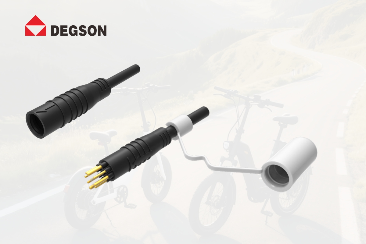
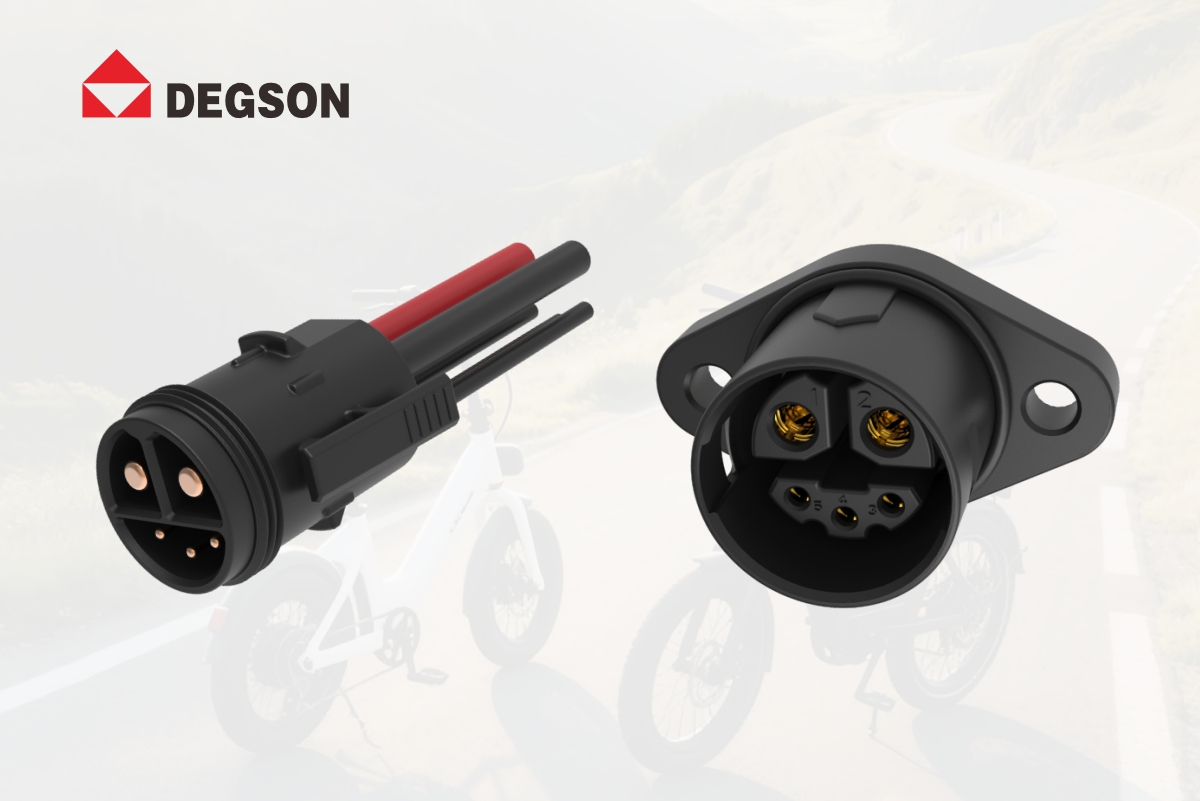
The DEGSON EBM e-motor connector is designed specifically for the motor interface environment. It operates over a temperature range of -25℃ to +80℃ with UL94-V0 flame retardancy, and its compact housing fits inside tight motor compartments. The EBM uses straight push-pull mating with a secure retention design suitable for motor-end vibration. The DEGSON EBIC motor power connector uses a press-locking structure that provides positive retention under vibration while remaining compact.
The problem:
An engineer selects a motor connector based on its rated current at room temperature, installs it on the motor, and finds that during prolonged operation the terminal temperature rises beyond acceptable limits. The connector is carrying its rated current — but at an ambient temperature far above the test condition.
How to calculate:
Connector current ratings are typically specified at 25℃ ambient. As ambient temperature rises, the allowable current decreases because the terminal temperature rise is added to the ambient temperature, and the sum must stay below the maximum allowable terminal temperature. For a motor connector operating in a 60℃-80℃ ambient environment, significant derating is required. Always request the derating curve from the supplier and calculate the usable current at the actual motor ambient temperature.
How DEGSON addresses it:
The DEGSON EBM and EBIC motor connectors are specified with operating temperature ranges that account for motor-end conditions. The DEGSON engineering team can provide derating guidance based on the customer actual motor ambient temperature and wire gauge. For higher-power motor applications, the DEGSON EBIC motor power plug and socket provides a higher current capacity with press-locking retention, suitable for motor-to-controller power and signal transmission.
The failure mode:
A motor connector that relies on friction alone will gradually work loose under continuous motor vibration. Unlike body connectors, which experience vibration transmitted through the frame, the motor connector is mounted on the motor itself — the source of vibration. This means higher amplitude, higher frequency vibration directly at the connector interface.
What to look for:
A motor connector should have a positive locking mechanism — a mechanical lock that engages on full mating and requires a deliberate action to release. Verify the extraction force specification, and confirm that the lock engages automatically rather than requiring a manual step. A connector that requires the assembler to remember to lock it will eventually be left unlocked at the motor.
How DEGSON addresses it:
The DEGSON EBM e-motor connector uses straight push-pull mating with secure retention suitable for motor-end vibration. The male connector comes with a protective cover that protects terminals during assembly and transit. The DEGSON EBIC motor power connector uses a press-locking design — compact and convenient, with positive retention under motor vibration. Both designs eliminate the friction-only loosening failure mode.
The problem:
Motor connectors with exposed terminals are vulnerable during assembly, transport and storage. A bent terminal, a contaminated contact surface, or a damaged seal before installation can cause failure after the connector is mated — and the root cause is invisible to the assembler.
The solution:
A protective cover on the male connector protects terminals during handling, assembly and transit. The cover is designed to be removed or flipped aside during mating, ensuring that the terminals are protected until the moment of connection. This is especially important for motor connectors, which are often installed in tight spaces where the connector may bump against the motor housing during assembly.
How DEGSON addresses it:
The DEGSON EBM male connector comes with a protective cover that protects the terminals during assembly and transit. The cover is removed during mating. The EBM compact structure and high space utilization make it suitable for installation in tight motor compartments. The DEGSON EBIC motor power connector also features a compact design with press-locking, suitable for motor-end installation where space is constrained.
The space constraint:
Motor housings are designed to be as small and light as possible. The connector must fit into the remaining space — often a narrow gap between the motor windings and the housing wall. A bulky connector may not fit at all, or may require modifying the motor housing, which adds cost and compromises structural integrity.
Soldering considerations:
Most motor connectors use soldered terminal wiring. Soldering at the motor end requires temperature control — excessive heat can damage the insulator or the motor windings. Use a temperature-controlled soldering iron, keep the temperature below 350℃ and soldering time under 3 seconds. For high-volume production, configure soldering fixtures to ensure consistency. Before production, train workers on terminal alignment and soldering temperature control.
How DEGSON addresses it:
The DEGSON EBM e-motor connector features a compact structure with high space utilization, enabling it to fit into the tightest motor compartments. It uses straight push-pull operation for quick connection during assembly. The DEGSON EBIC motor power plug and socket is also compact, with a press-locking structure that is small and convenient. DEGSON provides recommended soldering parameters and can support production fixture configuration for high-volume motor assembly lines.
1. Confirm the actual motor ambient temperature under maximum load, and calculate the derated current capacity at that temperature — do not use the room-temperature rated current.
2. Verify the locking mechanism: does it engage automatically? What is the extraction force? Is it rated for motor-end vibration?
3. Check the form factor: does it fit inside the motor housing? Does the male connector have a protective cover? Are soldering parameters provided?
-
Using the room-temperature rated current at the motor — ignoring thermal derating leads to terminal overheating.
-
Using a friction-fit connector at the motor — vibration gradually works it loose.
-
No protective cover on exposed terminals — bent or contaminated terminals cause post-installation failure.
-
Ignoring space constraints — a bulky connector does not fit the motor housing or requires housing modification.
-
Uncontrolled soldering — excessive heat damages the insulator or motor windings.
-
UL 4128 — Connector safety standard
-
IATF 16949 — Automotive quality management system
-
UL94 — Plastic flammability rating (V-0)
-
DEGSON micro-mobility connector product datasheets
When specifying a motor connector, evaluate thermal derating at the actual motor ambient temperature, vibration retention with a positive lock, compact form factor for the motor housing, and protective covers for terminal safety. Visit www.degson.com for the micro-mobility connector catalog, or contact the DEGSON engineering team for motor application design review and sample testing.


