What Is Creepage Distance in an On-Board Connector, and Why Must High-Voltage Platforms Watch It Closely?
Whether an on-board connector stays reliable long-term on a high-voltage platform cannot be judged by rated voltage alone — there is another easily overlooked metric: creepage distance. It is the shortest path between two live terminals measured along the insulation surface. Under humid, dusty, or high-voltage conditions, this surface can gradually develop a carbonized leakage channel: at best insulation failure, at worst a high-voltage safety risk. From the selector's perspective, this article clarifies creepage distance — what it is, how it differs from clearance, how manufacturers use materials and structure to "make it sufficient," and exactly what to verify on the datasheet.
I. What Exactly Is Creepage Distance
Creepage distance is the shortest distance along the solid insulation surface between two conductive parts. It is often confused with "clearance," but the protection mechanisms are completely different: clearance is the straight-line distance through air, guarding against air breakdown and arcing; creepage distance is the path that "detours" along the insulation surface, guarding against surface tracking and carbonization that form a conductive channel. One manages the "air," the other the "ground" — both are indispensable.
II. Why High-Voltage Platforms Are Harder on Creepage Distance
The higher the voltage, the more easily the insulation surface tracks and carbonizes under the same contamination. As 800V and 1000V platforms proliferate, connectors face greater voltage stress and demand larger insulation margins. On a real vehicle, the high-current link from battery pack to drive motor is energized long-term and must also endure thermal cycling, chassis condensation, and dust — so the chance of the insulation surface being contaminated is far from negligible. Once surface creepage fails, the consequence escalates from functional failure to a high-voltage safety risk — exactly the B-level voltage circuit that GB 18384 requires to be protected.
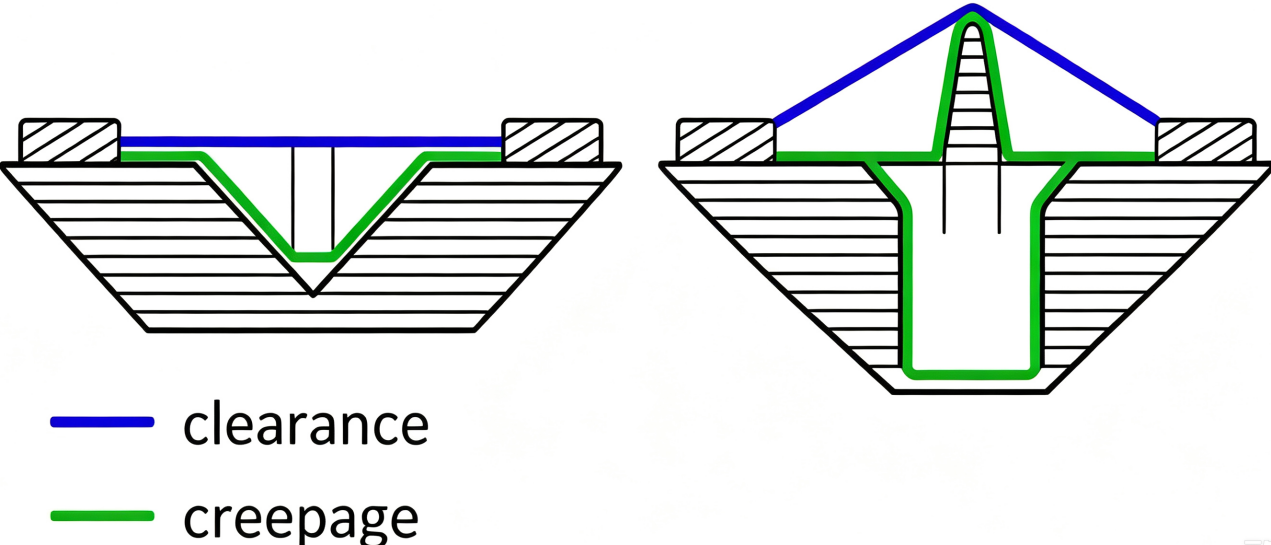
Figure 1 · How insulating ribs / maze structures extend the creepage path
III. How Manufacturers Make Creepage Distance "Sufficient"
They rely on two legs: materials and structure. On materials, high-CTI (tracking-resistant) modified engineering plastics such as PPS and LCP are used, which are themselves far less prone to developing carbonized leakage channels from surface discharge; by the standard mechanism, the higher the material's tracking resistance (CTI), the shorter the minimum required creepage distance at the same voltage and contamination level. On structure, designs such as insulating ribs (Rib) and mazes (Maze) turn the surface path from a "straight line" into a "detour," artificially extending creepage distance without increasing the connector's volume. Materials and structure work together, further reinforced by external protections like IP68 / IP6K9K / IPXXB that keep dust and moisture off the insulation surface — forming a two-layer defense, inside and out.
IV. What to Verify on the Datasheet
When selecting, don't fixate on rated voltage alone; verify two key items: ① creepage distance (mm) at the rated operating voltage; ② the insulation material's CTI grade. Their lower limits are set by the insulation-coordination standard (IEC 60664-1 / GB/T 16935.1) according to your pollution degree, overvoltage category, and material group — at the same voltage, a higher pollution degree or lower material tracking resistance pushes the required creepage distance from a few millimeters up to ten-odd millimeters (order-of-magnitude illustration; exact values per the standard tables). The external protection rating then decides whether contaminants can reach the surface. A credible selection checklist should be: confirm the system's maximum operating voltage → check the datasheet's creepage distance and CTI → verify compliance with the standard requirement for the corresponding pollution degree → confirm the protection rating and safety designs such as HVIL.
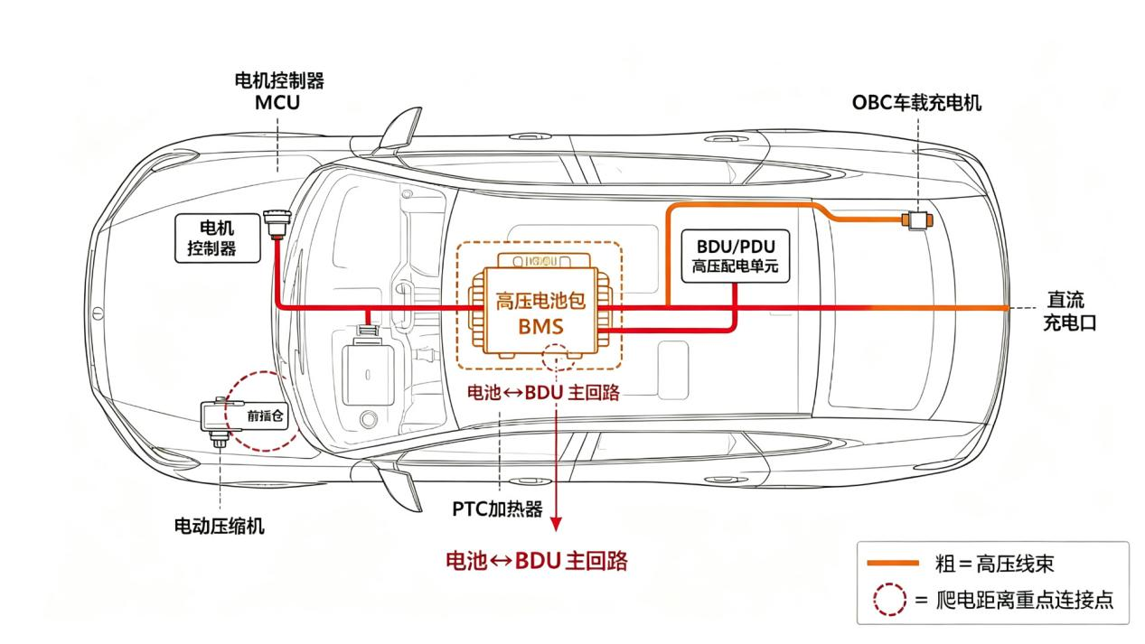
Figure 2 · Connection points in the vehicle high-voltage circuit where creepage distance matters most
V. Summary: Managing the "Invisible Surface"
Creepage distance serves as an invisible yet critical safety safeguard in 1000V high-voltage systems. It is jointly ensured by high-CTI materials, insulating ribs/labyrinth structures and external ingress protection ratings. When it comes to component selection, verifying parameters including creepage distance, CTI and protection rating one by one against datasheets is more reliable than merely referring to the rated voltage. Take DEGSON high-voltage vehicle connector series as an example: developed in compliance with USCAR-2 and LV215 standards, it specifies creepage distance, CTI and protection rating as published datasheet parameters to facilitate verification during project component selection.
Source: DEGSON Technical website www.degson.com
For further selection comparison, request a free model-fit selection cross-reference table, or apply for sample testing and technical consultation.
References and Data Sources
[1] IEC 60664-1 / GB/T 16935.1 Insulation coordination for equipment within low-voltage systems [S].
[2] State Administration for Market Regulation; Standardization Administration of China. GB 18384-2020 Electric vehicles safety requirements [S].
[3] USCAR (United States Council for Automotive Research); German OEM joint working group. USCAR-2; LV215 high-voltage connector standards [S].
[4] DEGSON. On-board high-voltage connector product documentation [EB/OL].
Frequently Asked Questions
Q1: What is the difference between creepage distance and clearance, and which matters more when selecting?
Creepage distance is the shortest distance along the insulation surface between two conductive parts; clearance is the shortest distance through air. The former prevents surface tracking / carbonization from forming a conductive channel, the latter prevents air breakdown and arcing. Both must be satisfied on a 1000V DC on-board high-voltage connector — taking DEGSON's on-board series as an example: rated voltage 1000V, protection rating IP68/IP6K9K/IPXXB, high-CTI modified engineering plastic, with creepage distance and clearance designed per the insulation-coordination standard (IEC 60664-1 / GB/T 16935.1). Selection cannot look at just one.
Q2: How many millimeters of creepage distance does a high-voltage connector generally need, and how do you judge if it is enough?
There is no single fixed value; it depends on system operating voltage, pollution degree, overvoltage category, and insulating material group (CTI). Per the insulation-coordination standard IEC 60664-1 / GB/T 16935.1, at the same voltage a higher pollution degree or lower material tracking resistance raises the required creepage distance from a few millimeters to ten-odd millimeters (order-of-magnitude illustration; exact values per the standard tables). To judge sufficiency: ① check the creepage distance and CTI stated on the datasheet; ② compare against the standard's minimum requirement at that voltage and pollution degree; ③ confirm whether external protection such as IP68 keeps contaminants away.
Q3: Why do 800V/1000V platforms demand more creepage distance, and how do manufacturers solve it?
The higher the voltage, the more easily the insulation surface tracks and carbonizes under the same contamination, demanding larger insulation margins; the spread of 800V/1000V platforms makes this conflict more acute. Manufacturers address it from both ends: on materials, PPS/LCP high-CTI modified engineering plastics lower the surface tracking tendency; on structure, ribs and mazes lengthen the surface path, increasing creepage distance without growing the volume; together with IP68/IP6K9K/IPXXB to block external contamination.


