How to Read UL Electrical Ratings on Terminal Blocks and Select the Right Model
Reading a UL rating correctly means asking two questions before you look at the number. First, which Use Group under UL 1059 does the "rated voltage" belong to — because the same 300 V terminal can be legal in one industry and not in another. Second, which wire size was the "rated current" tested with — because current is a temperature-rise result, not a physical ceiling. What the housing prints is often incomplete; the authoritative record is the certification page for that exact model number in UL Product iQ. This guide walks through both sides — voltage and current — and closes with how to verify the same parameters on terminal block case.
Voltage rating is set by clearance, creepage and Use Group
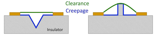
Under UL 1059, a terminal block's rated voltage is not chosen — it is the highest voltage the block's geometry can carry once its clearance (shortest through-air path between conductive parts) and creepage (shortest path along an insulating surface) meet the minimum spacings of the applicable Use Group. Clearance guards against air breakdown; creepage guards against surface tracking as dust and moisture build a conductive film over years of service. Change the Use Group and the same physical block can carry a different rated voltage — or fail to meet it.
How to read the UL 1059 Use Group table
The spacings below are measured at every live part, factory terminations included; when the block is soldered or wired in an end product, the spacings have to be re-evaluated at the assembly. Reproduced from UL 1059 Table 8.1 (values expressed in inches with millimetres in parentheses; see the standard for the full footnote text):
| Group | Application | Voltage (V) | Through air, in (mm) | Over surface, in (mm) |
|---|---|---|---|---|
| A | Service equipment, dead-front switchboards, panelboards | 51–150 | 1/2 (12.7) | 3/4 (19.1) |
| 151–300 | 3/4 (19.1) | 1-1/4 (31.8) | ||
| 301–600 | 1 (25.4) | 2 (50.8) | ||
| B | Commercial appliances, business & EDP equipment | 51–150 | 1/16ᵃ (1.6) | 1/16ᵃ (1.6) |
| 151–300 | 3/32ᵃ (2.4) | 3/32ᵃ (2.4) | ||
| 301–600 | 3/8 (9.5) | 1/2 (12.7) | ||
| C | Industrial, general | 51–150 | 1/8ᵃ (3.2) | 1/4 (6.4) |
| 151–300 | 1/4 (6.4) | 3/8 (9.5) | ||
| 301–600 | 3/8 (9.5) | 1/2 (12.7) | ||
| D | Industrial, devices with limited ratings | 51–300 | 1/16ᵃ (1.6) | 1/8ᵃ (3.2) |
| 301–600 | 3/16ᵃ (4.8) | 3/8 (9.5) | ||
| E | Terminal blocks rated 601–1500 V | 601–1000 | 0.55 (14) | 0.85 (21.6) |
| 1001–1500 | 0.70 (17.8) | 1.20 (30.5) | ||
| F | Industrial, alternative spacings per UL 508 §39 / UL 61800-5-1 | 51–1500 | As determined by evaluation | As determined by evaluation |
| G | LED lighting equipment | 51–300 | 1/16ᵃ (1.6) | 1/8ᵃ (3.2) |
| 301–600 | 1/16–3/16ᵃ (1.6–4.8) | 1/8–3/8ᵃ (3.2–9.5) |
Two footnote rules matter for reading the table. First, insulating-material slots or grooves 0.33 mm wide or less are ignored when measuring — the spacing effectively "jumps" the slot. Second, Group D and Group G ratings only apply where the load on any single circuit stays below 15 A at 51–150 V, 10 A at 151–300 V, 5 A at 301–600 V, or the block's maximum ampere rating, whichever is smaller. Group F blocks are evaluated under UL 508 §39 and UL 61800-5-1; the through-air and over-surface values are recorded per part number rather than read from a generic table.
Which Use Group fits which equipment
The Use Group encodes the end product the terminal will serve, not just its voltage class. A block certified in one group cannot be reused across another without a fresh evaluation.
Group A — service and distribution. Building service equipment, dead-front switchboards, panelboards and their fused-switch accessories — the equipment near the incoming supply that provides main control and disconnect. Because these are the highest-energy junctions in a building, Group A carries the widest spacings in Table 8.1.
Group B — commercial and business equipment. Office and commercial appliances: copiers, laser printers, high-capacity shredders, electronic data processing gear; commercial food-service kit such as blenders, espresso machines, microwaves and refrigerated display cases; commercial HVAC controls (programmable thermostats, BAS modules, fan-coil controllers); consumer-facing hardware such as vending machines, ATMs and ticket kiosks.
Group C — industrial, general. The default for factory-floor field wiring: motor controllers and drives (VFDs, soft starters); industrial control panels with DIN-rail feed-through blocks; PLC I/O and pluggable terminal blocks interfacing with plant sensors; industrial 12/24/48 V DIN-rail power supplies; transformers.
Group D — industrial with limited ratings. Compact industrial blocks that keep to the tight per-circuit current ceiling recited above; the small spacings unlock density but only under the ampere cap.
Group E — 601–1500 V. Higher-voltage terminal blocks; the exact evaluated voltage and installation limitations are on the individual certification record, not derived from the tier alone.
Group G — LED lighting. Terminals designed to sit inside LED driver and ballast enclosures, or in fixture wiring for outdoor and infrastructure lighting (smart street lighting, parking-garage and tunnel systems) where mains voltage may be 277 V or 480 V but per-circuit current is low.
Dielectric withstand: 1000 V + 2 × rated
The dielectric voltage-withstand test in UL 1059 applies a 45–65 Hz sinusoid at 1000 V + 2 × the rated voltage for one minute, between (a) live parts that are not conductively interconnected and (b) live parts and the mounting surface. A block rated 600 V therefore has to hold 2200 V for one minute without breakdown. If the datasheet quotes a "test voltage" that is not exactly this figure, ask what standard it was measured against — Hi-Pot values from other component standards are not equivalent.
Current rating is a temperature-rise value, not a physical limit
Under UL 1059 the current rating is the value at which the terminal-block temperature rise stays within 30 K over a 25 °C ambient while the block continuously carries that current. Temperatures are measured on every pole of the assembled block; change the wire size, and the same block earns a different current rating. The table below is the UL 1059 temperature-rise correspondence between conductor size and rated current — read it as "rated at this wire size", not "rated up to this current":
| Wire (AWG) | Rated current (A) | Wire (AWG) | Rated current (A) |
|---|---|---|---|
| 30 | 0.5 | 8 | 50 |
| 28 | 0.8 | 6 | 65 |
| 26 | 1 | 4 | 85 |
| 24 | 2 | 3 | 100 |
| 22 | 3 | 2 | 115 |
| 20 | 5 | 1 | 130 |
| 18 | 7 | 1/0 | 150 |
| 16 | 10 | 2/0 | 175 |
| 14 | 15 | 3/0 | 200 |
| 12 | 20 | 4/0 | 230 |
| 10 | 30 |
|
|
The practical implication: a block that reads "30 A" on its label may be a 30 A rating with 10 AWG, and a 20 A rating with 12 AWG. Selecting on the biggest number and wiring with something smaller means the block is operated outside its temperature-rise envelope.
Jumpers, end plates and accessories change the rating
UL evaluates the terminal strip as assembled, not the isolated base terminal. Jumpers, partitions, end plates, test plugs and fuse carriers all alter current path and spacing: a jumper with a cross-section below the base block's rating can pull the whole group below its printed ampere value; an end plate that reduces creepage over a mounting foot can force the block into a lower voltage tier. When cross-referencing series across brands, check the complete configuration — base block, accessories, mounting — against the target Use Group, not the base part number alone.
How to verify a DEGSON terminal on the datasheet and in Product iQ
DEGSON publishes each part number's rated voltage, rated current, wire range, standard reference (UL 1059 or IEC 60947-7-1 / IEC 61984) and certification list on the model's Technical Data tab at degson.com; the same page's Downloads tab holds the 2D PDF drawing and the CAD (STP/DXF) files.
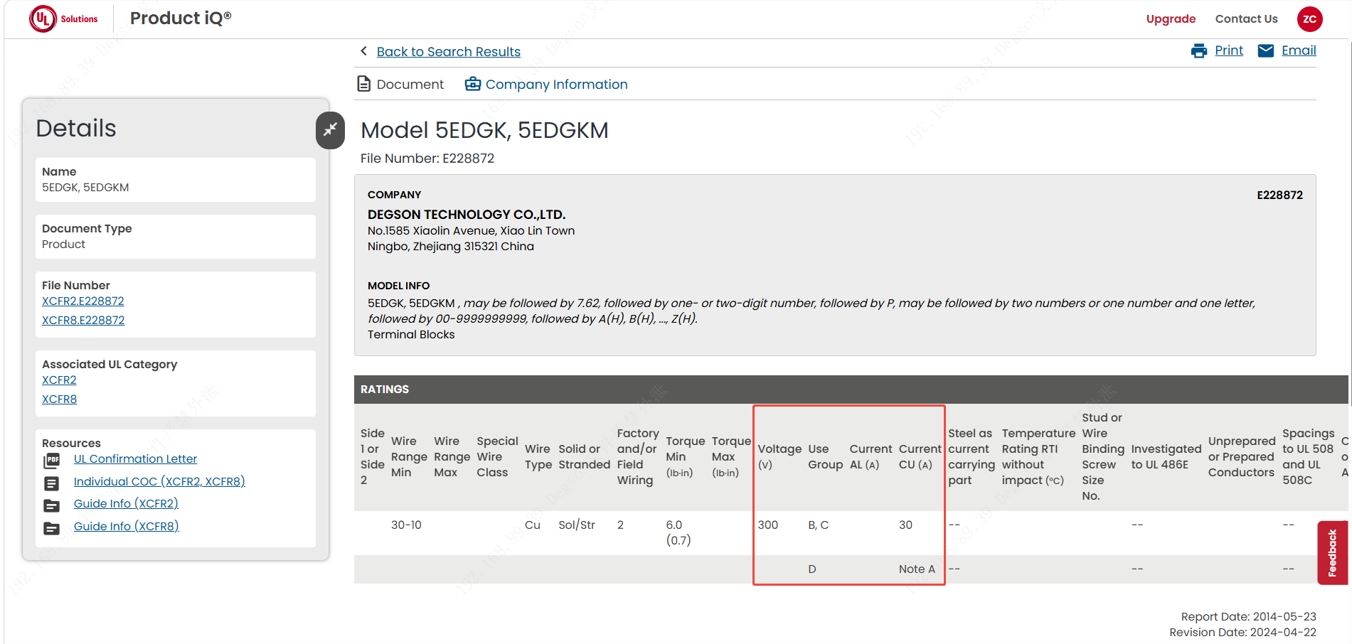
For the UL side of the record — Use Group, certified rating and evaluated conditions — search the file number or model in UL Product iQ, UL Solutions' free certification-lookup platform. If the two do not agree, the Product iQ record wins; ask the supplier to reconcile before releasing to production.
FAQ
Q1: The block is marked "300 V". Can I use it in a 300 V industrial control cabinet as-is?
Not until you check the Use Group. A 300 V block certified only under Group B (commercial / EDP equipment) carries far smaller minimum spacings than a Group C industrial block at the same voltage, and Table 8.1's rules prevent lifting it into industrial field wiring without a fresh evaluation. Look up the exact model in UL Product iQ, confirm it is listed under Group C (or a stricter group), and only then treat 300 V as usable in an industrial panel.
Q2: The datasheet says "30 A" — does that mean any wire will handle 30 A?
No. The 30 A number is the temperature-rise result measured with one specific conductor size. The same block wired with a smaller conductor is a different rating: paired with 10 AWG it may be a 30 A block; paired with 14 AWG the tested rating drops to 15 A. A datasheet that quotes an ampere value without the wire size is incomplete; ask the supplier for the tested wire size and clamping configuration before you specify it.
References
-
UL 1059, Standard for Terminal Blocks — the governing standard for terminal-block voltage, current, spacing and dielectric requirements: https://www.shopulstandards.com/ProductDetail.aspx?UniqueKey=32860
-
UL Product iQ — model-level certification lookup for Use Group, rated values and evaluated conditions: https://productiq.ulprospector.com/
-
UL Solutions — Dead-Front Replacement (Switchboard) Guide, definitions used in Group A: https://www.ul.com/thecodeauthority/knowledge/deadfront-replacement-guide
-
Battery Design — Creepage and Clearance primer: https://www.batterydesign.net/electrical/creepage-and-clearance/
-
DEGSON — Terminal-block minimum spacings for UL 1059, Q&A: https://www.degson.com/service/problem_details.html?id=233317&lang=en
Take the next step
Before you specify a terminal block, close the loop on both sides of the record. On the voltage side, confirm the target end product's Use Group (A / B / C / D / E / F / G) and the actual operating voltage, then trace clearance and creepage in the finished layout. On the current side, confirm the wire gauge you will actually land in the block, match it to the rated current in the datasheet, and check that any jumpers, end plates or fuse carriers you plan to add do not depress the assembly rating. Then verify against Product iQ. To apply the same checklist to a DEGSON block, browse the DS, DC/PC, STB, DGBSC and PCB families on degson.com, download the exact part-number datasheet and CAD, and request the UL and IEC test reports for the configuration you intend to install.


