Current and Temperature Rise: More Critical Than Rated Voltage for High-Voltage Vehicle Connectors
Whether an on-board connector stays reliable long-term on a high-voltage platform cannot be judged by rated voltage alone — there is another easily overlooked pair of metrics: current-carrying capacity and temperature rise. Current-carrying capacity is the maximum current a connector can pass continuously and safely; temperature rise (ΔT) is how much hotter the connector gets above ambient when energized. As 800V and 1000V platforms chase high-power fast charging and power density, current density and thermal margin decide whether the connection "runs a fever": at best insulation ages, at worst thermal runaway triggers a high-voltage safety risk.
Current-carrying capacity (often labeled Rated Current) is the steady current a connector can pass long-term without exceeding its temperature-rise limit, under specified ambient temperature, wire cross-section and cooling. It is bound to temperature rise: ΔT is the increase of terminal and insulation-surface temperature above ambient at thermal equilibrium. Joule's law ties them together — resistance at the conductor and contact interface generates I²R heat; higher current or higher resistance means more heat and higher ΔT. One governs "how much current can pass," the other "how hot it gets," and both are indispensable.
Higher voltage lowers the current needed for the same power (P=UI), so 800V does reduce current versus 400V; yet the battery-to-motor link and high-power fast-charging loop still carry hundreds of amperes continuously, with even higher power density. Connectors often sit in harsh engine-bay or chassis environments with thermal cycling, condensation and dust, where cooling is poor. Once ΔT runs away, consequences cascade: long-term overheating softens, tracks and carbonizes insulation plastic into a leakage path; more subtly, rising temperature relaxes contact springs, lowering contact force and raising contact resistance — a "resistance up → hotter → resistance up again" thermal runaway, exactly the B-level voltage circuit GB 18384 requires to protect.
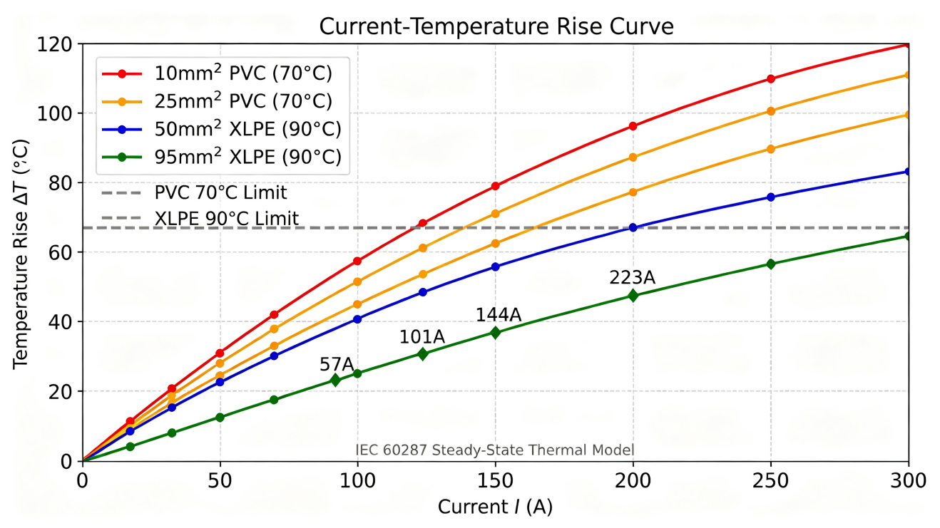
With two levers — materials and structure — plus a derating curve. On materials, high-temperature engineering plastics (PPS, LCP; flammability UL94 V-0) and low-resistance precious-metal/allowoy platings cut the contact resistance that is the heat source; per the common IEC 61984 basis, temperature rise at rated current is generally required to stay ≤45K. On structure, larger terminal/conductor cross-sections, optimized contact interfaces (crimp/screw/spring) and shorter current paths reduce heating at the same current; external protection such as IP68 / IP6K9K keeps dust and moisture off the insulation surface. The decisive piece is the derating curve: when ambient exceeds the baseline (e.g., 85°C) or wire cross-section shrinks, allowable current must be reduced along the curve — the real-world safety boundary.
Don't fixate on rated voltage; verify four items: ① rated operating current and its corresponding wire cross-section (e.g., current at 35mm² / 50mm²); ② temperature-rise limit at rated current (≤45K per IEC 61984 / USCAR-2 / LV215); ③ contact resistance and insulation resistance (e.g., insulation ≥500MΩ, withstand 3000V AC); ④ ambient-temperature range and derating curve (e.g., -40°C ~ +125°C). A credible checklist: confirm peak and continuous system current → read current-carrying/temperature-rise and derating from the datasheet → verify compliance with the relevant automotive standard → confirm protection grade and HVIL safety design.
Current-carrying capacity and temperature rise are an invisible yet critical line of defense in 1000V high-voltage safety, secured by low-contact-resistance materials, large-cross-section terminal structures and derating curves. Back to selection: checking rated current, temperature-rise limit, derating curve and protection grade item-by-item on the datasheet is far safer than reading a single rated voltage. For example, DEGSON on-board high-voltage connectors, developed to USCAR-2 and LV215, deliver 150A@35mm² and 200A@50mm² at 1000V DC, hold temperature rise within 45K per IEC 61984, and operate from -40°C to +125°C — convenient for project verification.
Source: Ningbo DEGSON Technology official site www.degson.com
For further matching, request a free model-adaptation selection table, or apply for samples and technical consultation.
[2] SAMR, SAC. GB 18384-2020 Electric vehicles safety requirements[S].
[3] USCAR; German OEM working group. USCAR-2; LV215 high-voltage connector standards[S].
[4] DEGSON. On-board high-voltage connector product data (DBYV/DBYR series)[EB/OL]. www.degson.com.


