Servo System Connector Topology: Interface Selection from Power Input to Encoder Feedback (2026)
A servo drive system spans power, control, and feedback paths that each carry fundamentally different electrical signals. The main AC input and UVW motor output require spring-clamp or screw terminals rated for 400–630 V and 10–20 A. The encoder feedback interface demands shielded, low-noise connections. Control, communication, and brake signal lines occupy a middle range between those extremes. Selecting the right connector for each position starts with mapping every interface to its place in the four-link servo topology — because fitting the wrong connector to a single node can cause intermittent faults that are difficult to trace and expensive to fix in a running production line.
Four High-Growth Industries Are Driving Servo Precision Higher
Servo control has shifted from a supporting technology to a design-critical requirement in four converging downstream sectors.
Photovoltaic and energy storage equipment requires coordinated multi-axis servo motion in stringing, lamination, and module-handling lines, where positioning accuracy directly affects production yield and scrap rate. Semiconductor back-end packaging — die bonding, wire bonding, and flip-chip operations — now targets sub-micron repeat accuracy with cycle times below 50 ms per operation, a performance level that only a closed-loop servo system can sustain. High-precision five-axis CNC machining centers run four to six servo axes simultaneously for spindle and feed drives; any connector intermittency on those axes translates directly to surface-finish defects and scrapped parts. Industrial robots, which represented the fastest-growing servo downstream segment in 2024 at roughly +15% year-on-year, pack six or more servo axes into a compact mechanical structure where every connector must survive continuous flex and vibration through tens of millions of cycles.
Across all four sectors, the connectors are not a commodity afterthought. A mismatch in voltage rating, inadequate contact retention under vibration, or missing shielding at the encoder interface can inject faults that appear as unexplained position deviations or nuisance alarms — failures that may only manifest after months of operation.
The Servo System Is Built Around Four Functional Links
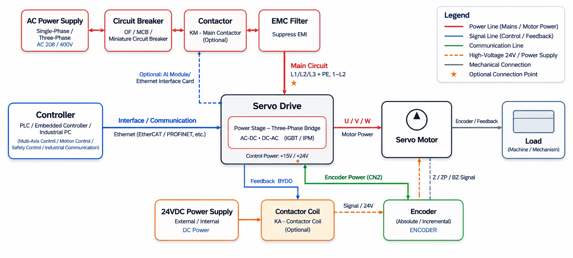
Before specifying any connector, it helps to trace the four functional paths that constitute a servo system.
Power supply chain: The AC grid — single-phase 200–240 V or three-phase 380–480 V — feeds a circuit breaker (short-circuit and overcurrent protection), a main contactor (main circuit switching), and an EMC line filter (conducted-interference suppression) before reaching the servo drive's AC input terminals, labeled L1/L2/L3 or L1/L2.
Drive core: Inside the servo drive, the AC supply is rectified into a DC bus, typically around 565 V DC on a 400 V three-phase supply. IGBT switches, controlled by a PWM algorithm, regenerate a three-phase variable-frequency output on the UVW terminals. The drive also exposes a DC bus terminal pair (P+/N−) and a brake resistor terminal (P/B or P/D) for energy dissipation during motor deceleration.
Servo motor: The motor converts the controlled electrical output from the drive into rotational or linear mechanical motion. It carries four distinct electrical interfaces: UVW dynamic power input, an encoder at the motor tail for position and speed measurement, an optional 24 V DC brake solenoid for holding position when de-energized, and an optional thermistor embedded in the winding for over-temperature protection.
Feedback path: The encoder returns a position and speed signal to the drive's CN2 port, closing the velocity and position loops in real time. The controller — a PLC, motion controller, or industrial PC — sends position, speed, or torque commands to the drive's CN1 port via pulse trains, ±10 V analog signals, or industrial Ethernet such as EtherCAT.
Each link in this chain presents distinct connector requirements. The following two sections address them in order of electrical severity.
Power Circuit Interfaces Impose the Strictest Connector Requirements
Main AC input — L1/L2/L3: Connectors on this rail carry the drive's full continuous input current. A 1 kW single-phase drive at 220 V draws approximately 5–7 A at full load; a 7.5 kW three-phase drive at 380 V draws roughly 16–20 A. The connector must meet IEC 61984 (for disconnectable terminals) or UL 1059 and sustain the rated voltage under overvoltage category III conditions, which requires verified creepage and clearance distances for the installation's pollution degree. Spring-clamp mechanisms are preferred over screw terminals on the PCB side because they maintain consistent clamping force across temperature cycles without requiring periodic re-torquing.
UVW motor output: The PWM-switched output on the drive's UVW terminals carries the same current as the input side but imposes additional stress from high dv/dt switching transients, sometimes exceeding 5 kV/μs. Insulation on this side must withstand repetitive voltage spikes, and the wiring from the drive to the motor needs shielding with the shield grounded at both ends to prevent PWM-induced interference from coupling back into the drive's control circuitry.
DC bus and brake resistor: The DC bus terminals (P+/N−) sit at approximately 565 V DC on a 400 V supply; the brake resistor connection must handle the peak current during regenerative braking, which can be several times the continuous motor current for short durations. Both terminal positions require connectors rated for high-voltage DC with the associated creepage distances for DC arc behavior, which differs from AC arc quenching.
Control, Communication, and Feedback Interfaces Each Carry Distinct Requirements
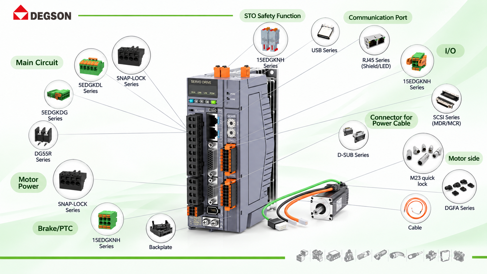
CN1 — command and communication interface: The CN1 port aggregates pulse-train inputs (step-direction or A/B/Z quadrature), ±10 V analog speed or torque command, and digital I/O lines for enable, alarm clear, and status signals. On drives equipped with industrial Ethernet (EtherCAT, PROFINET, EtherNet/IP), RJ45 ports replace or supplement CN1. Connectors here are not high-current, but they must maintain stable contact resistance across the drive's full vibration and temperature range; an intermittent contact on a run-enable line causes unexplained servo trips.
STO — Safe Torque Off: Modern servo drives implement STO to IEC 62061 (PLe, Cat 4) via a dedicated two-channel safety input. The connector for STO must be physically segregated from standard I/O to prevent accidental short-circuits between channels. Keyed or color-coded connector housings are a practical way to enforce this at the wiring stage.
CN2 — encoder feedback: The encoder cable runs from the motor tail to the drive's CN2 port, commonly via a D-SUB 9- or 15-pin connector, or an M23 circular connector on servo platforms following the Power Hybrid trend. Incremental encoders transmit differential RS-422 signals at 5 V; absolute encoders running Hiperface DSL, EnDat 2.2, or BiSS-C add protocol-layer data over the same cable. In both cases, the cable must be individually shielded, with the shield grounded 360° at both ends, to prevent position jitter from PWM interference coupling into the low-voltage signal. Contact resistance on encoder connectors must remain stable in the milliohm range to avoid signal degradation that appears as phantom position errors.
Brake and thermistor signals: The motor's 24 V DC brake solenoid typically draws 0.5–2 A continuously during operation (solenoid energized = brake released). Because the brake signal is a low-voltage power-class signal, it is routed with the motor power cable rather than the encoder cable. A 2- to 4-pin keyed connector on the motor tail handles brake power and the optional thermistor; the keying prevents polarity reversal during field replacement, which would de-energize the brake and drop the load.
DEGSON's 9EDGK Series: Verified at the Servo Drive Main Circuit Terminal
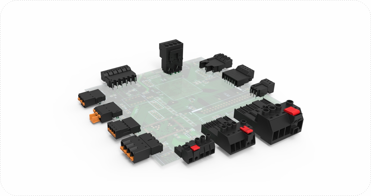
The DEGSON 9EDGK series is a pull-back spring PCB connector designed for power terminal connections in servo drives, inverters, and industrial power supplies. The 9EDGK-7.5 variant covers the electrical window required for drive main circuit and UVW interfaces:
The 630 V IEC (III/2) rating covers both 400 V three-phase drives and 200 V single-phase drives with margin. The 20 A contact rating accommodates servo drives up to approximately 7.5 kW on a 400 V three-phase supply without derating. For higher-power drives, the 5EDGKDL and DG65 series extend the current range and can be evaluated for the same terminal positions.
The pull-back spring mechanism — cage spring actuation via a push lever — eliminates the need for a screwdriver on the assembly line, reduces termination time per wire, and maintains a calibrated clamping force over the connector's service life independent of the technician's torque application. In servo drive cabinets that cycle through cold-start to sustained 40–50 °C ambient conditions, consistent clamping force is not cosmetic: fretting corrosion from micromotion at inadequately clamped contacts is a recognized failure mode in vibrating equipment.
A confirmed design-in reference: the DEGSON 9EDGK series is specified at the main circuit terminal block position in mainstream servo drive platforms in production, verifying that the series meets the PCB footprint, pitch, and electrical requirements for industrial servo applications.
To browse the full 9EDGK series, the datasheet and PCB footprint, or request a sample evaluation for your drive design, visit the DEGSON 9EDGK product page on degson.com.
Frequently Asked Questions
Can the 9EDGK-7.5 be used on both the AC input side and the UVW motor output side of a servo drive?
Yes, subject to verifying the current rating for your specific drive model. The 20 A IEC rating and 630 V (III/2) voltage rating cover both the L1/L2/L3 input and the UVW output for drives up to approximately 7.5 kW at 400 V three-phase. For the UVW side, also verify that the PCB layout provides sufficient creepage and clearance distances for the installation's pollution degree under PWM dv/dt conditions. Contact DEGSON's application engineering team for a drive-specific footprint and layout review.
Do encoder feedback interfaces require a different connector product from the main circuit terminals?
Yes. The CN2 encoder feedback interface carries low-voltage differential signals at 5 V (RS-422 or similar protocol) and requires shielded connectors with milliohm-level contact resistance — specifications that are unrelated to the power terminal requirements on the L1/L2/L3 and UVW rails. DEGSON offers D-SUB and M23 circular connector families for feedback interfaces; the correct choice depends on the encoder protocol, pin count, and drive platform. Consult DEGSON's technical team with your encoder type and connector drawing for a product recommendation.
References
- IEC 61984:2008 — Connectors — Safety requirements and tests (iec.ch/webstore)
- IEC 60068-2-6 — Environmental testing — Part 2-6: Vibration (sinusoidal)
- UL 1059 — Terminal Blocks (UL Product iQ: productiq.ulprospector.com)
- DEGSON TECHNOLOGY — 9EDGK-7.5 Product Page: degson.com


