How does overheat protection prevent safety accidents during the charging process?
The heat generated during the charging process is an unavoidable risk point for both vehicle charging and charging stations. The charging connector terminals, the internal power components of the control box, and the cables continuously generate heat under long-term high-current operation. Once the accumulated heat exceeds the material's tolerance limit, it may cause insulation aging, contact welding, and in extreme cases, a fire. Overheat protection, through real-time temperature monitoring, graded power reduction, and power-off protection, cuts off the heat source before an accident occurs, and is the core defense line for the thermal safety of charging equipment.
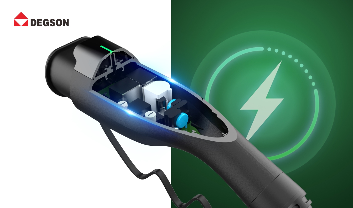
The Charging Heat Is Mainly Concentrated in Three Areas
The heat sources during the charging process are relatively concentrated, mainly distributed in the following locations:
- Charging connector plug-in terminals: The position where the plug connects to the vehicle socket or wall socket, with large contact resistance, terminal oxidation, or not being fully inserted can lead to excessive local temperature rise, which is a common hot spot in on-site accidents.
- Cable conductors: With small cable specifications, long cables, or cables not spread out, the cable itself heats up and combined with poor heat dissipation, causing the entire cable to rise in temperature.
- EVSE control box interior: Relays, PCB copper foil, and power components continuously generate heat under full load, and the risk is higher in summer exposure to the sun or in enclosed spaces with poor heat dissipation conditions.
In actual use, situations such as summer high-temperature exposure, loose plug oxidation, and charging with tangled cables will further increase the risk of heat generation. Many safety accidents are not caused by sudden failure of components, but by the inability to effectively control the heat for a long time. The DEGSON charging connector terminals adopt a copper alloy silver plating process, with a contact resistance lower than that of conventional tin-plated terminals, reducing the temperature rise at the terminals from the source.
Overheat Protection Is Achieved Through Hardware Sampling and Software Grading
The more mature overheat protection solution in the industry consists of temperature sampling hardware and software control logic, forming multiple layers of protection.
The first layer is the temperature measurement at the cable head end. A NTC or PT1000 temperature sensor is embedded near the charging connector terminals to monitor the temperature rise at the connection point and feed the data back to the EVSE main controller. When the temperature reaches the warning threshold, the equipment reduces power operation, and when the temperature reaches the protection threshold, it directly cuts off the output. For example, the DEGSON European standard charging connector has a NTC temperature sensor embedded in the cable head, monitoring the key areas of the plug, which can capture local abnormal high temperatures.
The second layer is the temperature monitoring inside the control box. Temperature sensors are placed at the heat sources such as relays, power components, etc., providing independent protection for excessive temperature inside the box. Even if the sensor at the cable head end is abnormal, the box end can still form a second line of defense. The DEGSON on-board charging product adopts a dual-point temperature measurement scheme at the cable head and control box ends to reduce the blind area of single-point monitoring.
The third layer is the software grading response logic. A reliable protection strategy is not typically "power off when the temperature is too high," but rather sets up three responses: mild temperature excess when reducing output current to maintain basic charging, and cutting off the output when the temperature continues to rise, balancing user experience and safety bottom line. Some low-priced products rely only on fuses or the self-tolerance temperature of components, without independent temperature sampling and grading logic, and cannot actively intervene in the early stage of temperature rise.
Overheat Protection Requires Coordination with Materials and Structural Design
Temperature sensors solve the problem of "detecting the problem," while material and structural design determine "how long it can withstand" and "whether it will spread."
The cable head shell should use UL94 V-0 level flame-retardant material to suppress flame spread in abnormal high temperatures; terminals use high-conductivity copper alloy and silver plating to reduce contact resistance, reducing heat generation at the terminals from the source. Cable specifications should match the rated current, and for 32A three-phase products, a 5×6mm² + 1×0.75mm² configuration is usually used. Insufficient cable diameter will cause continuous heating and frequent triggering of protection.
During the product development stage, DEGSON conducts simultaneous high-temperature aging and temperature rise cycle tests to verify the compatibility of sensor response, material heat resistance, and terminal heating, avoiding protection triggering delays or frequent malfunctions. Such validations can be completed in the pre-test facilities accredited by DEGSON's own VDE-TDAP and UL-CTDP, helping to identify thermal design issues before formal certification.
The Certification Standards Have Clear Test Requirements for Temperature Rise and Overheating Protection
Standards such as IEC 62196-1 and SAE J1772 specify the temperature rise limits and overheating protection functions for charging connectors. During the TUV and CE certification process, the laboratory will conduct the following tests:
- Rated load temperature rise test: Continuously power on at the rated current until the temperature stabilizes, measuring the temperature rise of each terminal and the housing, and ensuring it does not exceed the specified limit.
- Abnormal condition test: Simulate abnormal conditions such as poor contact and overload to verify whether the overheating protection can reliably act and cut off the output.
- Re-measurement after aging: Measure the temperature rise after 10,000 plug-in and unplugging cycles to confirm that the performance does not significantly deteriorate over a long period.
When selecting, it is recommended to request the supplier to provide the pages related to temperature rise in the certification report, rather than just looking at the certificate cover. Some products may hold the certificate but have an unreasonable sensor layout or improper software protection threshold settings, which may result in protection failure or frequent shutdowns in actual use. DEGSON's European standard charging cable has passed TUV, CE, and CB certifications, and the temperature rise and abnormal condition tests are completed in the TUV Rheinland laboratory. The reports can be checked.
When Selecting, Five Dimensions Can Be Used to Evaluate the Overheat Protection Capability
- Number of temperature measurement points: Prioritize the dual-point temperature measurement scheme at the cable head and control box ends. Single-point measurement has monitoring blind areas.
- Protection logic classification: Products with three-level response such as warning, power reduction, and power-off have a better user experience and safety than a single threshold power-off.
- Terminals and materials: Silver-plated terminals have a lower contact resistance than tin-plated terminals, and V-0 grade flame-retardant enclosures are a basic requirement.
- Completeness of certification report: Confirm that the TUV/CE report includes temperature rise tests and abnormal condition protection verification, and that the model is consistent with the purchased product.
- Temperature rise performance in high-temperature conditions: Pay attention to the temperature rise performance in high-temperature environments and after aging tests, rather than just looking at the laboratory data at room temperature. DEGSON and other manufacturers certified by IATF 16949 have relatively standardized material traceability and process control, and the thermal stability of long-term use is more guaranteed.
Overheat Protection Cannot Replace Proper Usage
It should be noted that overheat protection is a post-event intervention and cannot cover all risk scenarios. If the heat source is outside the sensor monitoring range, such as a loose internal wiring in a wall socket causing socket heating, the sensor at the cable head may not be able to sense it in time. In daily use, it is still necessary to pay attention to: ensure the plug is fully inserted, avoid crushing and winding of the cable during charging, regularly check if the plug has any burn marks or blackening, and avoid charging at full power in a sealed and exposed environment for a long time. Overheat protection is the safety bottom line, and proper usage is the first line of defense.
Q&A
Question: If the power supply frequently reduces power or cuts off during charging, is it a quality issue?
Answer: It may not be. It could be that the overheat protection has been triggered normally. We need to check whether the ambient temperature is too high, whether the plug is loose or oxidized, and whether the cable is poorly ventilated. If external factors are ruled out and the frequent actions still occur, it is recommended to contact the supplier to test the sensors and protection thresholds.
Question: Without a cable head temperature sensor, can the temperature measurement from the control box be sufficient?
Answer: The temperature measurement from the control box cannot promptly reflect the local high temperature of the cable head connection terminal. Terminal contact failure is a common hot spot. Dual-point temperature measurement is a more reliable solution.
Question: How long does it take for charging to resume after the overheat protection is triggered?
Answer: Different products have different strategies. Generally, it will automatically resume after the temperature drops below the safety threshold. Some products require manual re-plugging and unplugging to start. The specific details should be referred to the product manual.
Question: Will the TUV certification specifically test the overheat protection function?
Answer: Yes. The temperature rise test and abnormal condition test in the IEC 62196 series standards will verify whether the protection function operates as designed. Relevant data can be found in the certification report.


