Getting PCB Terminal Blocks Right on Dense 24V I/O Boards
For a 24V I/O board or module carrying digital I/O and 4–20 mA analog signals, the connections are low-current but numerous, so the practical choice is a fine-pitch PCB connector whose pole spacing fits your channel density, whose wire range brackets the thin signal conductors you actually land, and that carries the certification your target market needs — UL for North America, VDE/IEC for Europe. A pluggable push-in design adds fast, tool-light wiring and lets you unplug a block for service. Get pitch, wire range and certification right first; the brand decision comes after.
The wiring problem on a dense I/O board
A 24V I/O board rarely fails because of one big design decision. It gets tight one channel at a time. Every added input or output needs a landing point, a bit of copper, and enough clearance to seat a thin signal wire. As channel count climbs, the connector stops being a commodity and starts driving how the board is laid out, how it is assembled, and how field wiring behaves years later.
That is why the connector is worth choosing deliberately. The 24V and 4–20 mA signals themselves are undemanding — a few amps at most — but the density and serviceability constraints around them are not. A block that is a fraction too wide per pole, or missing the right certification, can force a re-layout late in the project, which is the most expensive time to find out.
Matching pitch and wire range to the board
Pitch is the first thing to lock down because it ripples through the whole layout. Signal I/O rarely needs the 5.0–5.08 mm spacing used for power terminals; a finer 3.5 mm pitch fits far more channels across the same board edge, and a two-row (high-density) body doubles that again. The trade is a narrower wire window and less creepage margin, so match the pitch to the signals you actually carry rather than defaulting to a wide power pitch.
Wire range then has to bracket what the board will actually land. Signal wiring typically runs 0.2–1.5 mm² (roughly 26–16 AWG), and a connector specified for that window seats cleanly and holds. Push a block near the edge of its range and you invite loose strands, marginal contact, and rework on the line. Match the range to the real wiring practice, not to a single nominal size on the schematic.
Why the certification scope decides design-in
Certification is where a good electrical choice can still stall. A board-level connector for equipment use is evaluated to specific standards — for a pluggable PCB connector, that is typically UL 1059 (terminal blocks) in North America together with IEC 61984 (connectors) internationally, rather than the IEC 60947-7-1 that governs DIN-rail terminal blocks. Confirm which standard the part is actually rated to.
The point for design-in is scope. A UL rating, an IEC rating, and a VDE approval each cover specific ratings, materials, and configurations — not "the whole family" by default. Before you commit, confirm the certificate applies to the exact series, current/voltage rating, and pitch you are placing, for the market you ship to. A UL rating can be checked by file number in UL Product iQ.
A practical way to shortlist
Once the constraints are explicit, shortlisting is quick. Compare candidates on the few parameters that actually gate the design:
| Selection criterion | What to check | Why it matters for a 24V I/O board |
|---|---|---|
| Pitch | Fine pitch for signal density (e.g. 3.5 mm, single or double row) | Fits more channels across the board edge |
| Rated current | Comfortably above the signal load (a few amps) | Margin for temperature rise and derating |
| Wire range | Brackets thin signal wiring (0.2–1.5 mm² / 26–16 AWG) | Clean seating, no loose strands |
| Rated voltage / insulation | Covers 24V plus transients, correct creepage | Long-term dielectric reliability |
| Connection & serviceability | Pluggable vs fixed; push-in vs screw | Wiring speed and unplug-for-service |
| Certification scope | UL 1059 / IEC 61984 / VDE for the exact series | Avoids late approval blockers |
| Operating temperature | Covers board ambient + rise | Prevents derating surprises in enclosed equipment |
Work top to bottom: fix pitch and wire range to your channel density, confirm current and voltage margin, decide whether you want a pluggable body for service, then filter by certification scope for your market. Whatever survives every row is a genuine candidate.
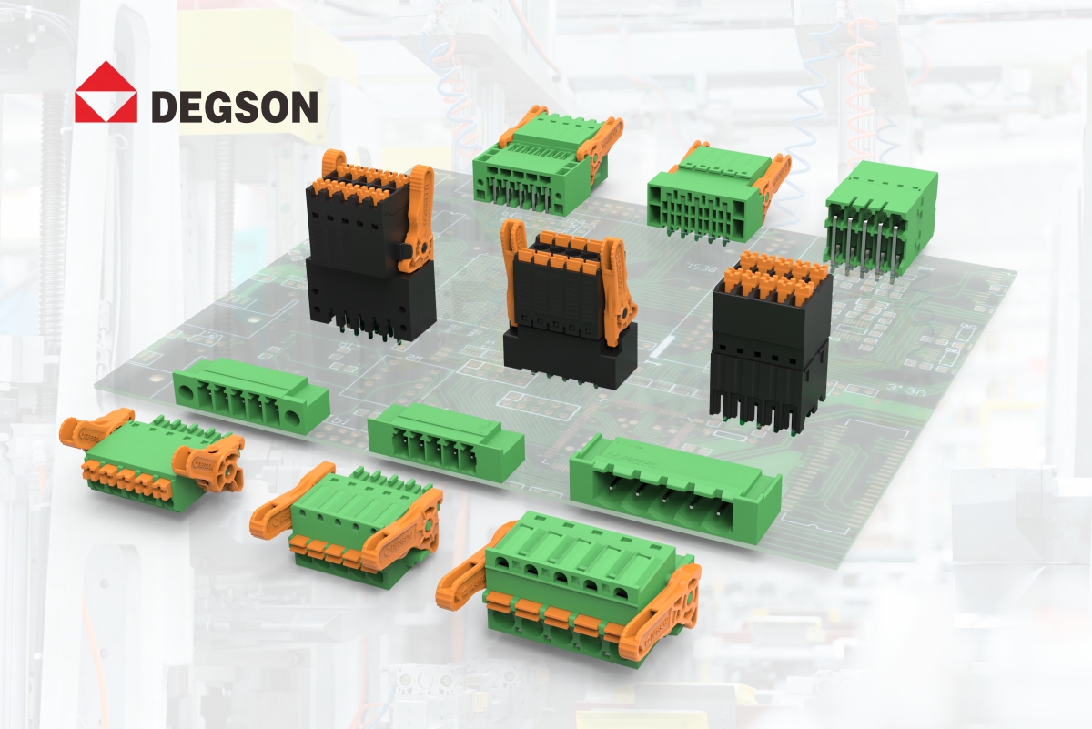
Where DEGSON PCB connectors fit
Once the method above narrows the field, DEGSON is one supplier worth putting on the shortlist for board-level signal connections. Its 15EDGKNH-3.5 series is a concrete example that maps onto the criteria above: a 3.5 mm-pitch, high-density double-row pluggable PCB connector using push-in spring connection, offered from 4 to 40 poles. It is rated 9.5 A / 250 V to IEC and 8 A / 300 V to UL, takes 0.2–1.5 mm² (26–16 AWG) solid or flexible wire, runs -40 °C to 105 °C (derating-dependent), and uses a PA66, UL 94 V-0 housing with tin-plated copper-alloy contacts. Its test standard is stated as IEC 61984 / UL 1059, with UL and VDE markings.
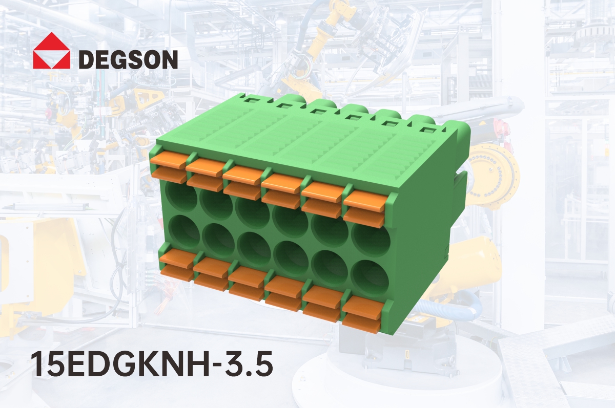
Those numbers fit the 24V I/O and 4–20 mA case well — low current, thin signal wire, and a fine pitch that packs channels — but they are the starting point, not the decision.
To show what verification looks like in practice, here is a DEGSON temperature-rise test on this series. A 15EDGKNH-3.5-12P plug, mated with its 15EDGRHC-3.5-12P header and tested to IEC 61984:2009, was loaded at 8 A per pole through 0.75 mm² solid conductors in a 40.4 °C ambient. The highest measured conductor temperatures were 78–95 °C across the poles — below the 110 °C material limit — so the sample passed:
| Position | Test current | Conductor | Ambient | Max measured temp | Limit | Result |
|---|---|---|---|---|---|---|
| 15EDGKNH (plug) | 8 A | 0.75 mm² | 40.4 °C | 78.3 / 90.5 / 89.1 °C | 110 °C | Pass |
| 15EDGRHC (header) | 8 A | 0.75 mm² | 40.4 °C | 91.4 / 94.5 / 91.6 °C | 110 °C | Pass |
The takeaway isn't the exact figures — it's that 8 A is well above any 24V I/O or 4–20 mA channel load, so at signal currents the part runs with wide thermal margin. For your own design, pull the datasheet, 3D STP and CAD DXF from the product page, confirm the certification file covers your target market, and ask for the test report and samples to trial on your board before design-in.
To move from shortlist to design-in, browse the 15EDGKNH-3.5 series and the wider PCB connector range on the DEGSON website: each product page carries the datasheet, 3D STP and CAD DXF, and you can request the IEC 61984 / UL 1059 test report and evaluation samples there to trial against your own 24V I/O board.
FAQ
Does a finer 3.5 mm pitch limit the current rating?
Somewhat — a finer pitch narrows the wire window and creepage, and typically comes with a lower current rating than a wide power pitch. For 24V I/O and 4–20 mA signals that is rarely a problem, since the loads are only a few amps. Check the datasheet rating against your worst-case channel current rather than assuming.
Which standard should a pluggable PCB connector be rated to?
For this class of part, look for UL 1059 (North America) together with IEC 61984 for connectors internationally — not the IEC 60947-7-1 that applies to DIN-rail terminal blocks. Confirm the exact series carries the marking for the market you ship to.
References
-
IEC 61984 — Connectors — Safety requirements and tests. IEC Webstore. https://webstore.iec.ch/en/publication/6223
-
UL 1059 — Standard for Terminal Blocks. UL Standards & Engagement. https://www.shopulstandards.com/ProductDetail.aspx?productId=UL1059
-
UL Product iQ — verify a UL file number and certification scope. https://productiq.ulprospector.com/


